The FPE-7039 MUX expansion module is designed to enhance the conventional features of the D7024 or FPD-7024/DS9400 Fire Alarm Control Panels (FACPs). This module connects directly to the FACP, supporting either two Class B multiplex buses or one Class A multiplex bus. When configured as two Class B multiplex buses, it allows for programming addresses from 9 through 255. If installed as one Class A multiplex bus, addresses 9 through 128 can be programmed.
Key Features and Enhancements:
- Increased Relay Outputs: The module significantly increases the number of relay outputs. For D7024/DS9400 control panels, it expands to 58 relay outputs, and for FPD-7024 control panels, it provides 59 relay outputs.
- Expanded History Buffer: It adds an additional 400 events to the history buffer, bringing the total to 499 non-volatile events. This extended capacity ensures that a comprehensive record of system activities is maintained.
- More System Users: The FPE-7039 allows for up to 100 system users, adding 84 PINs to the base system's capacity, which is beneficial for larger installations requiring more access control.
- Remote Programming: The module can be programmed remotely from a PC using Bosch's RPS Remote Programming Software, offering convenience and flexibility for system configuration and management.
Compatibility:
The FPE-7039 MUX expansion module is compatible with a range of Bosch Security Systems, Inc. control panels and modules:
- Active Control Panels:
- FPD-7024 Fire alarm control panels
- Legacy Control Panels:
- D7024 Fire alarm control panels
- DS9400 Control panels
- Active Modules:
- D7042 Multiplex eight-input remote module
- D7042B Multiplex eight-input remote module with enclosure
- D7044 Multiplex single-input module
- D7044M Multiplex mini single-input module
- D7050 Addressable photoelectric smoke detector
- D7050DH Addressable photoelectric duct smoke detector head
- D7050TH Addressable photoelectric smoke/heat detector
- D7050-B6 Smoke detector base
- D7052 Multiplex dual-input module
- D7053 Multiplex Input-output module
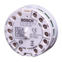
- FLM-7024-ISO MUX bus isolator module
- FMM-7045 Multiplex addressable manual pull station
- FMM-7045-D dual-action multiplex addressable manual pull station
- Note: Legacy products were investigated to comply only with UL864 8th edition.
Installation and Wiring:
Installation of the FPE-7039 module requires careful attention to safety and proper handling of static-sensitive components.
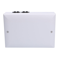
- Mounting the FPE-7039 Board:
- Ensure all power is removed from the FACP before making any electrical connections to prevent personal injury or equipment damage.
- If the FACP is already in an enclosure, remove it.
- Place the FACP on a flat surface with the component side facing up.
- Insert the four plastic standoffs into the mounting holes on the FACP without bending or flexing the board. Align the standoff tabs to avoid contact with module components.
- Firmly press the standoffs into the board, allowing the ears to expand.
- Mount the FPE-7039 board onto the standoffs, ensuring the connector pins are properly aligned with the FACP.
- Install the FACP back into its enclosure.
- Secure the FPE-7039's ground wire to the FACP using the mounting screw.
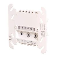
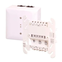
- Mounting the I/O Module:
- Insert the three plastic standoffs into the mounting holes in the FACP enclosure.
- Mount the I/O module into the FACP enclosure.
- Connect the wire harness of the I/O module to the terminal on the FPE-7039.
- Connect the yellow and green earth ground wire from the I/O module to the FACP's earth ground terminal.
Wiring the Loops:
The FPE-7039 can be configured with a single fault-tolerant Class A loop or as a pair of supervised Class B branches. Refer to the FPD-7024 Installation and Operation Guide (IOG) for detailed programming information.
- System Limits:
- Wire Type: Do not use shielded wire. Twisted-pair wire is not recommended but is acceptable if wire length is reduced by 50%.
- Data Points: When using graphs to determine system limits, data points in the "light area" are acceptable. Data points in the "middle area" depend on your configuration and must be verified with the battery calculation table. Data points in the "dark area" require changes in wire length or size, number of devices, or configuration.
- Process for Determining System Limits:
- Find the intersection of the desired number of devices and wire length/resistance on the first graph. If the point is in the light area, note available wire sizes (AWG or ISO) and proceed. If not, adjust.
- Look up the capacitance for the specific wire size/length/type.
- Check the intersection of capacitance and number of devices on the second chart. If the point is in the light area, your choices are acceptable. If not, adjust.
- Wiring Procedure:
- Determine the appropriate configuration (number and type of devices, wire size, and length).
- Run solid wire from the FACP to the device locations and connect the multiplex loop.
- Ensure the loop is disconnected from the FPE-7039 Module.
- Measure loop resistance by shorting the end of the farthest device in Class B or the return wire in Class A.
- Read the total resistance of all wires associated with the loop.
Technical Specifications:
- Environmental:
- Power:
- Current Draw (Alarm): 190 mA maximum
- Current Draw (Load, Class A): 100 mA maximum
- Current Draw (Load, Class B): 100 mA maximum for each bus
- Current Draw (Standby): 190 mA maximum
- Bus Voltage: 8.5 V to 13 V
- Wire Resistance (maximum): 50 Ω Class A or Class B
- Maximum Wire Length:
- Maximum Wire Resistance: 50 Ω at +20°F (+68°C), dependent on method and wire size used.
- Wire Length: 5950 ft. (1810 m), dependent on wire size and number of devices.
- Wire Capacitance: <0.12 µF (maximum per bus), dependent on wire size and number of devices.
- Note: The table provides capacitance in microFarads (µF), while graphs use nanoFarads (nF). For example, 0.12 µF = 120 nF.
Maintenance:
- NFPA 72 requires a complete system-wide functional test following any modifications, repairs, upgrades, or adjustments made to the system's components, hardware, wiring, programming, and software/firmware.
- Bosch Security Systems, Inc. is not responsible for improperly installed, tested, or maintained devices.