EasyManua.ls Logo

Bosch FLM-420-RLV1-E - User Manual

Bosch FLM-420-RLV1-E
28 pages
Go to English
To Next Page IconTo Next Page
Loading...
FLM-420-RLV1-E
F.01U.012.591
cs Instalační příručka
Vazební členy s nízkonapěťovými relé
da Installationsvejledning
Relæmoduler - lav spænding
de Installationsanleitung
Relaiskoppler für Kleinspannung
el Εγχειρίδιο εγκατάστασης
Δομοστοιχεία διασύνδεσης ρελέ χαμηλής τάσης
en Installation manual
Relay Interface Modules Low Voltage
es Guía de instalación
Módulo de relé de baja tensión
fr Manuel d’installation
Modules d’interface de relais basse tension
hr Priručnik za instalaciju
Niskonaponski modul relejskog sučelja
hu Telepítési útmuta
Kisfeszültségű relés csatolómodulok
it Guida di installazione
Moduli interfaccia relè a bassa tensione
nl Installatiehandleiding
Relaisinterfacemodules Laagspanning
pl Instrukcja instalacji
Moduły przekaźnika niskiego napięcia
pt Guia de Instalação
Módulos Interface de Relé de Baixa Tensão
ro Manual de instalare
Module de intervaţă cu relee de mică tensiune
ru Руководство по установке
Интерфейсные модули реле низкого напряжения
sl Navodila za namestitev
Nizkonapetostni moduli z releji
sv Installationshandbok
Relämodul lågspänning
tr Kurulum kılavuzu
Röle Alçak Gerilim Arabirim Modülleri

Table of Contents

Question and Answer IconNeed help?

Do you have a question about the Bosch FLM-420-RLV1-E and is the answer not in the manual?

Bosch FLM-420-RLV1-E Specifications

General IconGeneral
ModelFLM-420-RLV1-E
Housing MaterialPlastic
Protection CategoryIP 30
Operating Voltage24 V DC
Relay Outputs4
Operating Temperature-20 °C to 65 °C
Storage Temperature-25 °C to 85 °C
Air Humidity95% relative humidity, non-condensing
Weight150 g
Output Current1 A
TypeRelay Module

Summary

Technical Specifications and Compliance

Product Identification and Standards

Details CE marking, EN standards compliance, and the product's identification as an output module.

Address Setting and Configuration

DIP Switch Address Examples

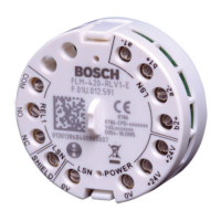
Illustrates address settings via DIP switches with examples for different configurations.

Compatibility Matrix for Addresses

Table showing compatibility of the module with various control panels based on address settings.

Detailed Address Setting Tables

Address Settings 0-127

Detailed binary representations for DIP switch settings from address 0 to 127.

Address Settings 128-254

Detailed binary representations for DIP switch settings from address 128 to 254.

Continued Address Setting Tables

Address Settings 128-254 (Continued)

Continuation of detailed binary representations for DIP switch settings from address 128 to 254.

Address Settings 214-254

Detailed binary representations for DIP switch settings from address 214 to 254.

Installation and Connection

Wiring and Mounting Diagrams

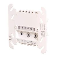
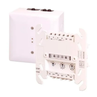
Illustrates LSN wiring, relay connections, and physical mounting procedures.

Operational Information

Safety Warnings and Notices

Provides critical safety notices, cautions regarding ESD, and danger warnings for live components.

Functional Description

Explains the module's purpose as a relay interface with a change-over contact output.

Address Setting Details

Summarizes address setting using DIP switches and refers to relevant figures and tables.

Connection Terminal Functions

Details the function of each terminal, including LSN, LSN-POWER, LSN-SHIELD, and REL1.

Technical Specifications

Lists detailed technical data including input voltage, current consumption, switching limits, and dimensions.

Related product manuals