12 en FLM-420-RLV1-E
F.01U.013.004 | 6.0 | 2010.06 Bosch Sicherheitssysteme GmbH
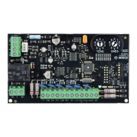
Functional description
The FLM-420-RLV1 Relay Interface Module Low Voltage has a change-over contact relay to provide a potential free
output contact.
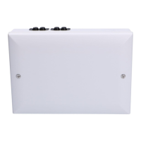
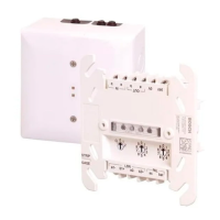
The FLM-420-RLV1-E type in-built can be flush mounted in standard device boxes in accordance with EN 60670;
alternatively, it can be installed in the devices (see Figure 6 to Figure 7, Page 7).
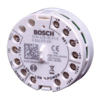
Address setting
Address setting is carried out using the 8 DIP switches and a suitable pointed object (see Figure 1 to Figure 4, Page 4
and the following tables).
Connection
Technical specifications
NOTICE!
Installation must only be performed by authorized and specialized personnel!
The connected device must have a minimum activation time of 20 ms.
CAUTION!
Electrostatic discharge (ESD)! Electronic components could become damaged.
Ground yourself using a wrist strap or take other suitable actions.
DANGER!
Live components and stripped cable! Risk of injury from electric shock.
The system must be current-free during connection work.
Address (A) Operating mode
0 Loop/stub in LSN improved version mode with automatic addressing
1 — 254 Loop/stub/T-tap in LSN improved version mode with manual addressing
255 = CL Loop/stub in LSN classic mode (address range: max. 127)
Terminals Function
LSN: a1- | b1+ | a2- | b2+ LSN in / LSN out
LSN-POWER: 0 V | 0 V | +24 V | +24 V LSN power supply (support points to loop through)
LSN-SHIELD Cable shielding (if present)
REL1: COM | NO | NC Change-over relay (COM/NO contact/NC contact)
Figure 5 Page 7 shows the relay connected as
- NO contact: continuous line
- NC contact: dotted line.
Relay 1 low voltage relay (NO/COM/NC)
LSN input voltage 15 to 33 V DC
Max. current consumption from LSN 1,75 mA
Max. switched current and voltage (resistive load) 1 A / 30 V DC
Min. switched current and voltage 0.01 mA/10 mV DC
Minimum activation time of the connected device > 20 ms
Permissible wire diameter
0.6 to 2.0 mm
2
Permissible operating temperature / storage temperature -20 °C to +55 °C / -25 °C to +80 °C
Permissible rel. humidity <96%, non-condensing
Protection class as per IEC 60529 IP 30
Classes of equipment as per IEC 60950 Class III equipment
Housing material and color ABS + PC blend, signal white (RAL 9003)
Dimensions approx. 50 mm x 22 mm (Ø x H)
 Loading...