EasyManua.ls Logo

Bosch FPE-8000-SPC User Manual

Bosch FPE-8000-SPC
18 pages
To Next Page IconTo Next Page
Page #1 background imageLoading...
Page #1 background image
AVENAR panel 8000 | AVENAR panel 2000 |
AVENAR keypad 8000
FPE‑8000‑SPC | FPE‑8000‑PPC | FPE‑8000‑FMR |
FPE‑2000‑SPC | FPE‑2000‑PPC
en Quick user guide
Bosch Sicherheitssysteme GmbH
Robert-Bosch-Ring 5
85630 Grasbrunn
Germany
www.boschsecurity.com
© Bosch Sicherheitssysteme GmbH, 2020
F.01U.364.479 | 07.2020 | 4.0
The default password is “000000”, please ask your in-
staller to change this password.
Note: The panel controller may only be operated by
trained personnel. The personal access code (consisting
of user ID and password) must not be made known to
third parties.
DEF
2
1
ABC
3
4
5
GHI
JKL
MNO
7
8
9
PQRS
TUV
WXYZ
*
0
#
F2
F3
F1
F1
F1F1
Fire
0
Control
0
Fault
0
Bypass
0
Status
* Favourites
Bypass off
Multicriteria sensor
Bypass on
Red strobe
Bypass off
Red strobe
Bypass off
Multicriteria sensor
Bypass off
Multicriteria sensor
Bypass off
Multicriteria sensor
If you are already logged on, press to open
the pre-configured personalized menu. To log off, press
again and confirm with OK .
Programmable elements
Function keys
There are three functions keys which are freely program-
mable with frequently used functions of the panel. If a
function key is active it is marked with a green bar. Please
ask your installer to enter the configured function of the
respective key here:
F1
F2
F3
Alarm and fault status LEDs
There are two status LEDs which are programmable for a
self-defined alarm and self-defined fault/disablement.
Please ask your installer to describe the configured device
and status of the respective LED here:
Change time and date
To change the date and time of the panel press
- Further functions - Change date / time and
enter the correct values via the keypad.
Day- and night mode
The manner in which an incoming alarm is handled de-
pends on whether the system is in day or night mode.
Night mode has the highest security level. Depending on
the configuration, the alarm message is generally transmit-
ted to the fire department without a delay. Signaling
devices and transmission devices to the fire department or
fire protection systems are activated.
If a panel is set to day mode, it is possible to delay the
transmission of the first alarm signal to prevent false
alarms. Therefore an alarm must be acknowledged within
a certain time. The transmission device to the fire depart-
ment is not activated in this case. During the delay, the
cause of the alarm message can be checked within a con-
figured investigation time to ensure it is correct.
If the investigation time passes by without any further user
input (alarm trigger or reset) the transmission to the fire
department is activated automatically.
The following symbols on the status bar show which mode
the panel is switched to. In the case of networked panels,
a night-/day combination icon is displayed on panels in
night mode, if at least one panel in the network is in day
mode.
Standalone Network
Night mode Panel is in
night mode
All networked panels
in the network scope
are in night mode
Day mode Panel is in
day mode
-
Night-/day
combination
- Panel is in night
mode but at least
one other panel in
the network scope is
in daymode
To switch between day- and night mode press the current
symbol in the status bar and select either Switch to day
mode or Switch to night mode.
Fire
0
Control
0
Fault
0
Bypass
0
Status
Switching off internal buzzer
DEF
2
1
ABC
3
4
5
6
GHI
JKL
MNO
7
8
9
PQRS
TUV
WXYZ
*
0
#
F2
F1
F3
F1
F1F1
F2
F2F2
F3
F3F3
Fire
2
Control
2
Fault
0
Bypass
0
Status
Bypass
Block
Diagnostics
Maintenance
Configuration
Switch to day mode
Further functions
Control
Monitoring
Reset
* Level 3 logged in
1. Press to temporarily switch off the in-
ternal buzzer.
Display history
In the history log, all data about particular events or
device types is stored sorted by date and time. To display
only particular data, filters can be set.
To show the history log press - Diagnostics -
History log.
Select language
Press to access the main menu. Press “1” on
the alphanumeric keypad. Confirm the appearing query
with OK and select the required language from the list.
Further information
For detailed information on the operation of the fire panel
please refer to www.boschsecurity.com.
11 | 12 | 13 | 14 |
15 | 16 | 17 | 18 |
Question and Answer IconNeed help?

Do you have a question about the Bosch FPE-8000-SPC and is the answer not in the manual?

Bosch FPE-8000-SPC Specifications

General IconGeneral
TypeFire Alarm Control Panel
ModelFPE-8000-SPC
ManufacturerBosch
Zones8
NAC Outputs4
Power Supply Voltage24 V DC
Event LogUp to 10, 000 events
Battery BackupYes
CommunicationEthernet, RS-232

Summary

Panel Overview

Status LEDs

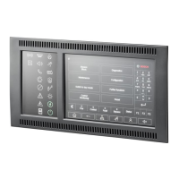
Indicators showing the operational status of the panel.

Information Bar

Displays general information and system status.

Status Bar

Shows current mode and active functions.

Open Start Menu

Accesses the main menu options.

Go Back

Navigates to the previous screen or menu.

Networked Panels

View networked panels and establish remote connections.

Alarm Zones Control

Manage and monitor all alarm zones.

Log-in and Menu Access

Access personalized menus and user functions.

Silence Internal Buzzer

Temporarily mutes the internal buzzer.

Programmable Function Keys

Keys that can be assigned to specific functions.

Support Information Display

Shows technical support or device details.

Status LED Meanings

Fire Alarm LED

Indicates a fire alarm condition.

Evacuation Ongoing LED

Signals that an evacuation process is active.

Fire Alarm Transmission LED

Shows activation of fire alarm transmission.

Fire Protection Equipment LED

Indicates activation of fire protection systems.

Maintenance Mode LED

Indicates the system is in maintenance mode.

Day Mode/Delays LED

Signals active day mode or configured delays.

General Disabled LED

Indicates a general disabled state.

General Fault LED

Indicates a general fault condition.

Fire Detector Fault/Disabled LED

Shows fault or disabled status for fire detectors.

Signaling Device Fault/Disabled LED

Indicates fault or disabled status for signaling devices.

Alarm Transmission Device Fault/Disabled LED

Shows fault or disabled status for alarm transmission devices.

Fire Protection Output Fault/Disabled LED

Indicates fault or disabled status for fire protection outputs.

Power Fault LED

Indicates a power supply fault.

Power Available LED

Signals that power is available.

System/Panel Fault LED

Indicates a fault in the system or panel.

System Operation LED

Shows that the system is operational.

Programmable Alarm LED

User-configurable LED for custom alarm indication.

Programmable Fault/Disabled LED

User-configurable LED for custom fault/disablement.

Handling Alarms

Alarm Message Type

Identifies the category of the alarm.

Alarm Location Description

Provides details on where the alarm originated.

Alarm Detector Address

Specifies the zone and subaddress of the triggering detector.

Number of Triggering Detectors

Indicates how many detectors initiated the alarm.

Alarm Message Number

Unique identifier for the alarm message.

Alarm Group Activation

Details activated groups and outputs during alarm.

Evacuation Procedures

Evacuation Zones and Groups

Overview of available evacuation zones and notification appliance groups.

Evacuation Status Colors

Meaning of background colors indicating evacuation status.

Controlling Evacuation Zones

How to start, stop, or manage evacuation for specific zones.

Resetting Alarms

Acknowledge Alarm

Initial step to acknowledge an active alarm.

Silence Signaling Devices

Temporarily stops sounders and optical signals.

Reset Alarm

Final step to clear the alarm condition.

Handling Faults

Fault Message Type

Identifies the category of the fault.

Fault Element Type

Specifies the type of element experiencing the fault.

Fault Element Address

Provides the zone and subaddress of the faulty element.

Fault Message Number

Unique identifier for the fault message.

Fault Location Description

Details the location of the element causing the fault.

Fault Element Actions

Steps to acknowledge and reset a fault condition.

Log On and Log Off

User Login Process

Procedure for logging into the panel using user ID and password.

Password Management

Information regarding default passwords and security practices.

Personalized Menu Access

How to open and use the pre-configured user menu.

User Log Off

Procedure for securely logging out of the panel.

Programmable Elements

Function Key Configuration

Details on programmable function keys and their assignments.

Programmable Status LEDs

Information on configuring status LEDs for custom indications.

Date and Time Settings

Change Date and Time

Instructions for modifying the panel's date and time.

Day and Night Mode

Mode Operation

How day and night modes affect alarm handling and transmission.

Mode Indicator Symbols

Explanation of symbols indicating standalone and network day/night modes.

Switching Day/Night Mode

Procedure for switching between day and night modes.

Buzzer and History Log

Switching Off Internal Buzzer

How to temporarily silence the internal buzzer.

Displaying History Log

Instructions to access and view event history data.

Language Selection

Select Language

Procedure for selecting the desired user interface language.

Further Information

Related product manuals