Applications Manual Bosch Greenstar | 67
Bosch Thermotechnology Corp.
Data subject to change
Appendix A: Quick Set-up Guide for Room Controllers
CRC100 control set-up:
For single zone application where CRC100 is connected directly to the boiler:
Ź Set A.1 value to “CO”
Note: Please consult the installation manual for a complete overview of the controller settings and proper installation. The
following guide is not a substitute for the installation manual.
For a multi- zone application where CRC100 is connected to a CZM100:
Ź Set H.C on each CRC100 to the appropriate zone number (1 thru 8)
CRC200 control set-up:
For single zone application where the CRC200 is connected directly to the boiler:
ŹSet DHW to “yes – pr. pump” if indirect tank is connected to the system
Ź Set “Heat System” to “High Temp” or “Low Temp” depending upon system requirement
Ź Set “Max Supply Temp” to appropriate maximum temperature for the system
For a multi- zone application where CRC200 is connected to a CZM100:
Ź Set HC on each CRC200 to the appropriate zone number (1 thru 8)
For CRC200 located in Zone #1:
Ź Set DHW to “yes – pr. pump” if indirect tank is connected to the system
Ź Set “Heat System” to “High Temp” or “Low Temp” depending upon zone requirement
Ź Set “Max Supply Temp” to appropriate maximum temperature for the zone
For CRC200 located in zones 2 thru 8:
ŹSet “Heat System” to “High Temp” or “Low Temp” depending upon zone requirement
ŹSet “Max supply Temp” to appropriate maximum temperature for the zone
Coding and Connection to…..
CZM100 #1 CZM100 #2 CZM100 #3
Heating
Zone
Number
Pump
contacts
1
2
3
4
5
6
7
8
1
1
1
2
2
2
3
3
-
-
-
-
-
-
-
-
-
-
-
-
-
-
-
PZ1
-
-
PZ2
PZ3
PZ1
PZ2
PZ3
PZ1
PZ2
Coding and Connection to…..
CZM100 #1 CZM100 #2 CZM100 #3
Heating
Zone
Number
Zone
Valve
Contacts
1
2
3
4
5
6
7
8
4
4
4
5
5
5
6
6
-
-
-
-
-
-
-
-
-
-
-
-
-
-
VZ1
-
-
VZ2
VZ3
VZ1
VZ2
VZ3
VZ1
VZ2
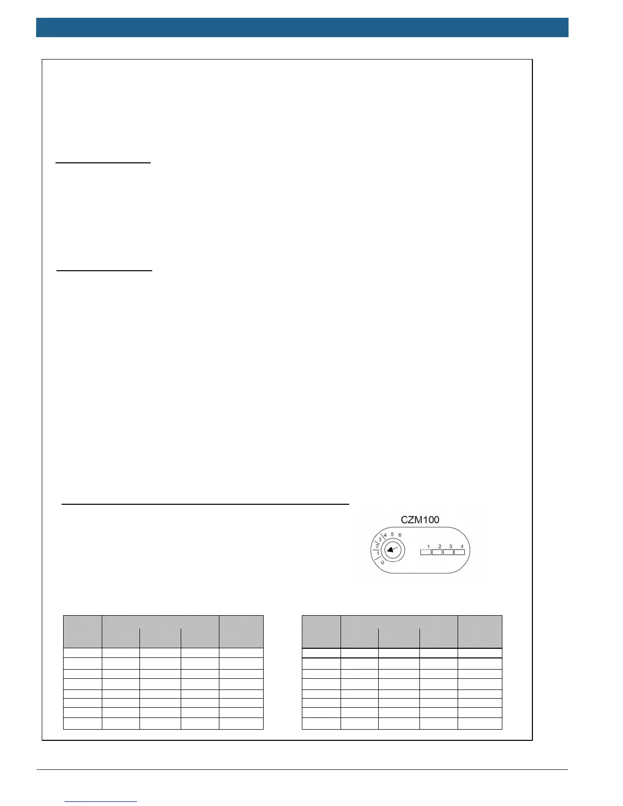
Zone number and corresponding pump/Zone valve output on CZM100:
The CZM100 can support systems using Pumps or Zone valves but
not both. The maximum number of CZM100 in a system is 3. The
CZM100 address can be set by adjusting the potentiometer screw
on the front of the CZM100 (see image right). Address #1 thru #3
is for systems using pumps. Address #4 thru #6 is for systems
using zone valves. Charts below show the heating zone number
and the corresponding pump or zone valve contacts on the
CZM100.
Pumps