EasyManua.ls Logo

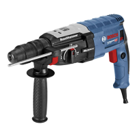
Bosch GBH 2-28 DFV User Manual

Bosch GBH 2-28 DFV
21 pages
To Next Page IconTo Next Page
Page #1 background imageLoading...
Page #1 background image
INSTANDSETZUNGSHINWEISE
REPAIR INSTRUCTIONS
INSTRUCTIONS DE REPARATION
INSTRUCCIONES DE REPARACION
Änderungen vorbehalten. Unsere Erzeugnisse werden stets
dem neuesten technischen Stand angepaßt. Deshalb behalten
wir uns Änderungen vor.
Modifications. Our products are constantly modified to meet
new technical standards. We therefore reserve the right to
alter data and specifications without prior notice.
Modifications. Nos produits sont continuellement adaptés aux der-
nières nouveatés techniques et les dates sont données sous réserve
de changement.
Modificationes. Nuestros fabricados van siendo adaptos constante-
mente a las últimas conquistas téchnicas. Por ello, tenemos que reser-
varnos el derecho de introducir modificationes en los datos téchnicos.
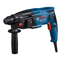
Bohrhammer
Rotary Hammer
Marteau perforateur
Martillo perforador
Typ 3 611 B67 200 = GBH 2-28 DFV
Attention: Repair, modification, and testing of power tools must be carried out in
accordance with the generally recognised principles of engineering practise. Safety
regulations according to DIN VDE, CEE, AFNOR and further regulations applicable in
individual countries must be observed.
Beachten: Instandsetzung, Änderung und Prüfung von Elektrowerkzeugen sind
fachgerecht durchzuführen. Die Sicherheitsvorschriften nach DIN VDE, CEE,AFNOR und
weitere in den einzelnen Ländern gültigen Vorschriften sind einzuhalten.
Obsérvese: La reparación, modificación y verificación de herramientas electricas mano
debe efectuarse en forma técnicamente correcta. Respetar las normas de seguridad
segun DIN VDE, CEE, AFNOR, asi como otras disposiciones vigentes en los distinos
paises.
Attention: La remise en état, la modification et le controle des outils électriques doivent
etre ef- fectués par des personnes qualifiées. Il convient de respecter les prescriptions
de sécurite selon DIN VDE, CEE, AFNOR, ainsi que les réglementations en vigueur dans le
pays concerné.
3 611 B67 200 - D01 (2012-01)
Robert Bosch GmbH
.
PowerTool Devision
.
PT-AS/DOC
.
70745 Leinfelden-Echterdingen
Question and Answer IconNeed help?

Do you have a question about the Bosch GBH 2-28 DFV and is the answer not in the manual?

Bosch GBH 2-28 DFV Specifications

General IconGeneral
Impact Energy3.2 J
Impact Rate at Rated Speed0 - 4000 bpm
Rated Speed0 - 900 rpm
Weight3.1 kg
Tool Dimensions (Height)216 mm
Tool HolderSDS-plus
Drilling Diameter in Concrete with Hammer Drill Bits4 - 28 mm
Optimal Drilling Diameter in Concrete with Hammer Drill Bits8 - 16 mm
Drilling Diameter in Concrete with Core Cutters68 mm
Drilling Diameter in Masonry with Core Cutters68 mm
Drilling Diameter in Steel13 mm
Drilling Diameter in Wood30 mm
Power SourceCorded Electric
Vibration Level11.0 m/s²

Summary

Repair Instructions

General Safety and Compliance

Ensures repair, modification, and testing adhere to recognized engineering practices and safety regulations.

Disassembly Procedures

Tools and Preliminary Checks

Requires standard tools and performing a preliminary power supply check.

Assembly based on Visual Aids

Disassembly follows exploded views, cut-away drawings, and repair instructions.

Disassembly Steps

Step 3.3: Component Removal

Illustrates removal or adjustment of specific components.

Step 3.4: Component Arrangement

Shows the arrangement of a series of components.

Step 3.5: Component Operation

Demonstrates an operation involving a specific component with angle indication.

Step 3.6: Part Identification

Identifies specific parts with numerical labels.

Step 3.7: Fastener Installation

Shows installation with torque specification for fasteners.

Component Handling Steps

Step 4: Component Removal

Illustrates the removal of components using tools.

Step 4.1: Component Removal

Shows another component removal sequence with tools.

Step 4.2: Component Replacement

Illustrates replacement of components.

Step 4.3: Housing Removal and Torque

Details removal of housing with torque specification.

Step 5.0: Safety Clutch Check

Procedure to check the safety clutch.

Step 5.1: Safety Clutch Check Details

Provides details and criteria for safety clutch check.

Assembly and Tooling Steps

Step 5.2: Auxiliary Tool Dimensions

Provides dimensions for an auxiliary tool for assembly/disassembly.

Step 5.3: Component Assembly

Illustrates the assembly of specific components.

Step 5.4: Component Assembly Sequence

Shows a sequence for assembling components.

Step 5.5: Component Assembly Method

Demonstrates a method for assembling components using tools.

Step 5.6: Auxiliary Tool Usage

Illustrates the usage of an auxiliary tool for a specific task.

Component Assembly Steps

Step 5.7: Component Installation

Shows manual installation of a component.

Step 5.8: Component Disassembly

Illustrates the disassembly of a component stack.

Step 5.9: Component Installation

Shows installation of components using tools.

Step 6.0: Gearbox Assembly

Illustrates the assembly of gearbox components.

Step 6.1: Gear Assembly

Shows assembly of gears.

Step 6.2: Gear Installation

Illustrates the installation of gears.

Mechanical Component Steps

Step 7.0: Component Attachment

Illustrates attachment of components with screws.

Step 7.1: Component Assembly

Shows assembly of components with torque specification.

Step 7.2: Component Disassembly

Illustrates disassembly of components.

Step 7.3: Component Replacement

Shows replacement of a component.

Step 7.4: Gear Assembly

Illustrates assembly of a gear mechanism.

Step 7.5: Gear Installation

Shows installation of a gear.

Electrical and Gearbox Assembly

Step 8.0: Housing Screw Installation

Illustrates screw installation into housing with torque.

Step 8.1: Internal Component Assembly

Shows assembly of internal components.

Step 8.2: Electrical Connections

Details electrical connections with torque specifications.

Step 9.0: Gearbox Assembly

Illustrates assembly of the gearbox housing.

Step 9.1: Gear and Rotor Assembly

Shows assembly of gears and rotor with torque.

Step 9.2: Seal Assembly

Illustrates the assembly of a seal.

Rotor and Housing Assembly

Step 9.3: Rotor Assembly

Shows assembly of the rotor and related parts.

Step 9.4: Rotor and Brush Assembly

Illustrates assembly of rotor and brush holder.

Step 9.5: Tool Holder Assembly

Shows assembly of tool holder components.

Step 10.0: Housing Screw Installation

Illustrates screw installation into housing with torque.

Step 10.1: Housing Assembly

Shows assembly of housing components.

Step 10.2: Component Installation

Illustrates installation of components.

Assembly Procedures

General Assembly Guidelines

General guidelines for assembly, including cleaning, replacing parts, and using original spares.

Step 21.1: Auxiliary Tool Usage

Illustrates usage of an auxiliary tool for assembly.

Step 21.2: Screw Installation

Shows screw installation with torque specification.

Step 22: Component Identification

Identifies specific components for assembly.

Step 22.1: Sleeve and Component Assembly

Illustrates assembly of sleeves and other components.

Component Lubrication and Wiring

Step 23: Component Lubrication

Instructions for lubricating components by immersion in oil.

Step 23.1: Component Lubrication

Further instructions for lubricating components in oil.

Step 23.2: Component Insertion

Illustrates insertion of components.

Step 24: Electrical Connections

Shows electrical connections with torque for securing.

Step 24.1: Wiring Installation

Illustrates wiring installation.

Step 24.2: Installation Position Check

Ensures correct installation position of components.

Wiring and Gear Installation

Step 24.3: Installation Position Check

Check for correct installation position.

Step 24.4: Wiring Routing

Illustrates routing of wiring.

Step 24.5: Wiring Routing

Shows routing of wiring with color codes.

Step 24.6: Wire Connection

Illustrates wire connection with torque.

Step 24.7: Housing Lubrication

Instructions for lubricating sliding surfaces of the housing.

Step 25.1: Gear Lubrication

Instructions for lubricating gears and sliding surfaces.

Step 25.2: Gear Lubrication

Further instructions for lubricating gears.

Step 25.3: Gear Installation

Shows gear installation with position check.

Gear and Tool Assembly

Step 25.4: Auxiliary Tool Dimensions

Provides dimensions for an auxiliary tool for assembly.

Step 25.5: Gear Assembly

Illustrates assembly of gears.

Step 25.6: Auxiliary Tool Usage

Shows usage of an auxiliary tool.

Step 25.7: Gear Assembly

Illustrates assembly of gears.

Step 25.8: Component Insertion

Shows manual insertion of components.

Step 25.9: Gear Assembly

Illustrates assembly of gears with torque.

Component Greasing and Lubrication

Step 26: Component Greasing

Illustrates greasing of a component with grease.

Step 26.1: Component Greasing

Shows greasing of components with lubricant.

Step 26.2: Lubrication and Torque

Instructions for oil lubrication and torque application.

Step 26.3: Sliding Surface Lubrication

Lubrication of sliding surfaces.

Step 26.4: Component Immersion

Illustrates component immersion in oil.

Step 26.5: Internal Greasing and Immersion

Internal greasing and component immersion in oil.

Step 27: Component Assembly

Step 27.1: Vice Jaws and Spring Gap

Use of vice jaws and ensuring spring gap alignment.

Step 27.2: Auxiliary Tool and Piston

Using auxiliary tool and handling old piston.

Assembly and Lubrication Details

Step 27.3: Lubrication and Assembly

Lubrication and assembly of parts with grease.

Step 27.4: Lubrication and Assembly

Lubrication and assembly of components.

Step 28: Housing Assembly

Step 27.5: Auxiliary Tool Dimensions

Provides dimensions for an auxiliary tool for assembly/disassembly.

Step 27.6: Sleeve and Component Assembly

Illustrates assembly of sleeve and components.

Step 27.7: Safety Clutch Check

Check release torque of safety clutch and replacement criteria.

Step 27.8: Lubrication and Assembly

Lubrication and assembly of parts.

Step 28.1: Housing Assembly

Shows assembly of the housing.

Housing and Cavity Procedures

Step 28.2: Auxiliary Tool and Mounting Pin

Use of auxiliary tool and mounting pin for assembly.

Step 28.3: Cavity Filling

Instructions to fill cavity between sealing lips.

Step 28.4: Pre-Greased Components

Illustrates components delivered pre-greased.

Step 28.5: Component Lubrication

Shows lubrication of components.

Lubrication and Assembly Steps

Step 28.6: Gear and Housing Lubrication

Lubricate parts and gear compartment.

Step 28.7: Component Assembly

Illustrates assembly of components.

Step 28.8: Part Identification and Lubrication

Identifies parts and shows oil lubrication.

Step 28.9: Component Operation

Demonstrates component operation with angle indication.

Component Arrangement

Step 29: Component Arrangement

Shows arrangement of components.

Step 29.1: Component Installation

Illustrates installation of components.

Step 29.2: Component Replacement

Shows replacement of components.

Step 29.3: Component Installation

Illustrates manual installation of components.

Step 29.4: Component Assembly

Shows assembly of components.

Final Checks

Step 30: High Voltage Test

Procedure for performing a high voltage test and safety compliance.

Step 31: Performance and Test Run

Perform test run, impact test, and electrical/mechanical checks.

Lubrication Guide

Gearbox and Part Lubrication

Lubricate specific parts (30g) and the gear compartment (pos. 340).

Gear Teeth Lubrication

Lubricate all gear teeth using specified grease.

Oil Immersion and Greasing

Instructions for oil immersion and greasing of components.

Sealing Lip Cavity Filling

Fill the cavity between sealing lips with lubricant.

Related product manuals