6 720 817 281 (2017/05) Greentherm 9800 SEO 160/199 | SECO 199
36 | Troubleshooting
10.12 Factory default settings
Restore factory values for P1 Max. Power
▶ Access to menu P1 Max. Power.
▶ Press symbols or to select Reset Parameters.
▶Press the symbol .
The display blinks to confirm change.
▶Press the symbol .
The factory default values for P1 are restored.
Restore factory values for P2 Max. Power
▶ Access to menu P2 Min. Power.
▶ Press symbols or to select Reset Parameters.
▶ Press the symbol .
The display blinks to confirm change.
▶ Press the symbol .
The factory default values for P2 are restored.
10.13 Converting Gas Type
▶ Turn Off the appliance.
▶ Remove the front cover from the appliance (section 3.3.2).
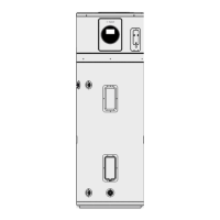
▶ Remove the four screws that retain the cover plate to the
gas manifold, see fig. 31 (plate in grey color).
Fig. 31 Gas manifold
▶ Remove metal plate and seal.
▶ The 3 restrictor plates should be pre-assembled onto their
tray, but if loose in box, follow installation instruction, as
shown in fig. 32 [1].
▶ Insert the LP conversion plate in the appropriate location
shown in Fig. 32 [2].
CO
2
range (%) Max. CO level
(measured)
Greentherm 9800 SE/SEC O
199 000 BTU
Nat. Gas
max. input P1 8.5 % - 8.9 % < 250 ppm
min. input P2 2.3 % - 2.5 % < 30 ppm
LP Gas
max. input P1 9.8 % - 10.2 % < 250 ppm
min. input P2 2.8 % - 3.0 % < 30 ppm
* Values above are for climate controlled conditions.
Inputs such as gas pressure, heating value of the gas,
humidity and temperature of combustion air all impact
CO and CO
2
values. Changes in these inputs can result in
different CO and CO
2
values on the same appliance.
Table 17 CO
2
& CO target numbers
CO
2
range (%) Max. CO level
(measured)
Greentherm 9800 SE O
160 000 BTU
Nat. Gas
max. input P1 8.6 % - 9.0 % < 250 ppm
min. input P2 3.3 % - 3.5 % < 30 ppm
LP Gas
max. input P1 9.7 % - 10.1 % < 250 ppm
min. input P2 3.6 % - 3.8 % < 30 ppm
* Values above are for climate controlled conditions.
Inputs such as gas pressure, heating value of the gas,
humidity and temperature of combustion air all impact
CO and CO
2
values. Changes in these inputs can result in
different CO and CO
2
values on the same appliance.
Table 18 CO
2
& CO target numbers
DANGER: Fatal accidents!
Before any service or testing in the
appliance,
▶ Turn off the appliance.
▶ Disconnect the power supply cord.
▶ Shut off the gas supply.
The gas type conversion must only be carried
out by a qualified contractor.
CAUTION:
▶ All three flow restrictors and seal must
be assembled according to the Fig. 32,
to assure correct appliance
performance.

 Loading...