6 720 816 815 (2018/08)Greentherm T9800 SE 160/199 | SEC 199
Troubleshooting | 59
8.12 CO emissions check
In case air/gas combustion adjustment has been performed
check emissions using reference values in tables 25 and 26.
8.12.1 Access to measuring port
▶ Open a hot water tap and let the appliance work for 2 or 5
minutes.
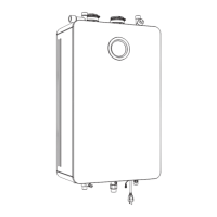
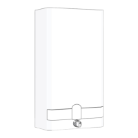
▶ Remove the screw from the flue adaptor on the left side of
the appliance, as seen in fig. 60.
▶ Insert analyzer probe into the measuring port. The tip of the
probe should be in the center of the flue pipe (approx 1.5"
inserted). Avoid air gaps between probe and measuring
port as they can alter readings.
Fig. 60 Measuring port
8.12.2 CO
2
and CO values
8.12.3 Returning to Service
▶ Remove the analyzer probe and insert the screw into the
flue adaptor.
▶ Touch the symbol to exit service menu.
The appliance is ready for normal operation.
Allow the appliance to stabilize before
performing CO readings.
Let appliance warm up and wait for 2 or 5
minutes for each CO readings.
This will avoid wrong CO readings.
CO
2
range (%) Max. CO level
(measured)
Greentherm T9800 SE / SEC
199 000 BTU
Nat. Gas
max. input P1 8.4 % - 9.0 % < 250 ppm
min. input P2 N/A < 100 ppm
LP Gas
max. input P1 9.7 % - 10.4 % < 250 ppm
min. input P2 N/A < 100 ppm
* Values above are for climate controlled conditions.
Inputs such as gas pressure, heating value of the gas,
humidity and temperature of combustion air all impact
CO and CO
2
values. Changes in these inputs can result in
different CO and CO
2
values on the same appliance.
Table 25 CO
2
& CO target numbers
CO
2
range (%) Max. CO level
(measured)
Greentherm T9800 SE
160 000 BTU
Nat. Gas
max. input P1 8.5 % - 9.1 % < 250 ppm
min. input P2 N/A < 100 ppm
LP Gas
max. input P1 10.0 % - 10.6 % < 250 ppm
min. input P2 N/A < 100 ppm
* Values above are for climate controlled conditions.
Inputs such as gas pressure, heating value of the gas,
humidity and temperature of combustion air all impact
CO and CO
2
values. Changes in these inputs can result in
different CO and CO
2
values on the same appliance.
Table 26 CO
2
& CO target numbers
 Loading...