58300000202443_ARA_EN_C JANUARY 2018 Service Manual for Bosch 800 Series Built-in Wall Ovens
Page 23 of 43
Copyright by BSH Home Appliances Corporation 1901 Main St ▪ Suite 600 ▪ Irvine, CA 92614 800 944-2904
This material is intended for the sole use of BSH authorized persons and may contain confidential and proprietary information. Any unauthorized review, use, copying, disclosure, or distribution in any format is prohibited.
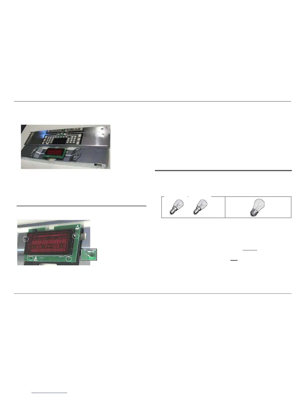
6. Remove the screw in the bottom center of the panel, which
secures the panel to the carrier directly behind it.
7. Separate the carrier from the front panel assembly.
8. Reassemble the control panel using the new front panel
service assembly.
9. Reattach the control panel, restore power, and test operation.
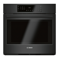
6.4.2 Replacing the Display Module
The display module is secured to the control panel carrier with
four nylon spacers (standoffs).
1. Remove the front panel as described in Replacing the Front
Panel Service Assembly section.
2. Using pliers, gently straighten each metal tab so that they align
with the slots in the display board, then lift the board off the
tabs.
3. Position the new display board so that the slots in the board
align with the four metal tabs, and firmly push the board
downward until it is securely in place.
4. Slightly re-twist each of the four metal tabs.
5. Reassemble the control panel.
6. Reattach the control panel to the side trim and vent trim.
7. Restore power and test operation.
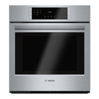
6.5 Cavity Lights
Each 30” oven cavity uses one incandescent 40W appliance bulb with
a standard Edison base. Each 27” oven cavity uses two 25W
incandescent bulbs (25WPRE14), with a European base.
Replacement bulbs may be purchased locally.
On double ovens, lights are either on or off in both cavities; it is not
possible to operate cavity lights independently.
The cavity light(s) can be turned on in two ways: by pressing Oven
Light or opening the oven door. If Oven Light had not been pressed to
turn light(s) on prior to opening the oven door, the light(s) will turn off
when the door is closed. If Oven Light had been pressed to turn
light(s) on prior to opening the oven door, the light(s) will remain on
after the door is closed.
In other words, the Oven Light switch overrides the door.