100 en | Alarms and Relay Connections VG4 Modular Camera Series
F.01U.216.010 | 8.0 | 2011.02 Installation Manual Bosch Security Systems, Inc.
2. From the AutoDome main menu select Alarm Setup>Inputs Setup, and set Alarm Input #
to N.O. See the table below for contact and condition details.
6.3.2 Configuring a Normally Closed Non-supervised Alarm
1. Connect the alarm to the appropriate input (1 through 7) and ground at the AutoDome.
Figure 6.4 N.C. Normally Closed Non-supervised Connections
2. From the AutoDome main menu select Alarm Setup>Inputs Setup, and set Alarm Input #
to N.C. See the table below for contact and condition details.
6.4 Alarm Outputs
The AutoDome incorporates two (2) types of alarm outputs: a dry contact relay and three (3)
open collector outputs or transistor outputs.
6.4.1 Configuring a Dry Contact Relay
The dry contact relay acts like an on/off switch. It has a maximum voltage rating of 2 A @
30 DC.
1. Connect the appropriate stripped wire to the AutoDome COM connector.
2. Connect the appropriate stripped wire to the N.O. or N.C. connector, depending on your
requirement.
6.4.2 Configuring an Open Collector Output
Outputs 1, 2, and 3 are open collector types. These outputs must be connected to a positive
voltage between 5 and 32 V to complete the circuit, with a maximum voltage rating of 32 VDC
@ 150 ma.
1. Connect the appropriate stripped wire to the open connector (1, 2, or 3) of the
transistor.
2. Connect the appropriate stripped wire to the ground (GND) connector.
AutoDome Programmed N.O.
Circuit Alarm Indication
Open Normal
Closed Alarm
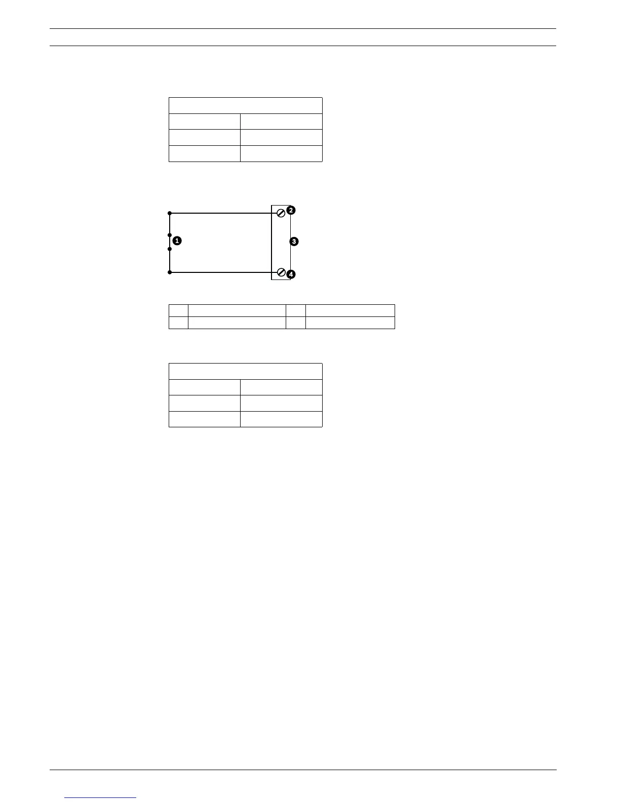
1 Dry Contact 3 Dome Connector
2 Alarm Inputs 1 to 7 4 Ground
AutoDome Programmed N.C.
Circuit Alarm Indication
Open Alarm
Closed Normal
 Loading...