Do you have a question about the Bosch LBB 1930 and is the answer not in the manual?
Covers reading instructions, retaining them, following warnings, cleaning, and using attachments.
Addresses water exposure, stable mounting, and proper ventilation for safe operation.
Details power sources, grounding, cord protection, overloading, and preventing object entry.
Emphasizes professional servicing, using specified replacement parts, and damage assessment.
Relates to safety checks post-service and lightning protection measures.
Clarifies the meaning of warning, caution, and note symbols used throughout the manual for user guidance.
Warns against opening the unit when connected to mains due to exposed non-insulated parts.
States that there are no user-serviceable parts inside, requiring qualified personnel for service.
Presents a block diagram illustrating the internal connections and components for LBB1930 and LBB1935 models.
Displays a block diagram showing the internal architecture and connections for the LBB1938 model.
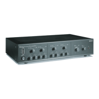
Details the controls and indicators located on the front panel of the booster amplifiers.
Illustrates the front panel layout and controls for the LBB1930 and LBB1935 models.
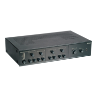
Shows the front panel layout, including specific indicators for the LBB1938 model.
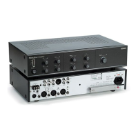
Describes the rear panel connectors and controls for the LBB1930 and LBB1935 booster amplifiers.
Provides a diagram of the rear panel connections for the LBB1930 and LBB1935 models.
Details the rear panel connectors and controls specific to the LBB1938 booster amplifier.
Illustrates the rear panel layout and connections for the LBB1938 booster amplifier.
Explains how to set output voltages (70V/100V) using internal fuses.
Shows the internal fuse holders (F701, F702) used for setting output voltage selection.
Warns against inserting fuses into both F701 and F702 simultaneously to prevent damage.
Outlines steps for mounting the booster amplifiers in a 19" rack, including ventilation requirements.
Provides visual guidance for installing the LBB1930, LBB1935, and LBB1938 units in a rack.
Instructions for connecting a 24 Vdc backup power supply or batteries.
Illustrates the DC supply connection for LBB1930/1935 and LBB1938 models.
Stresses the necessity of an in-line fuse in the connection cable for safety.
Guides on connecting line inputs and using loopthrough for signal distribution.
Shows how to connect line inputs and loopthrough between different amplifier models.
Explains how to adjust the output level using the volume control next to the line input.
Details connecting priority input and using control terminals for the LBB1938.
Illustrates priority input and control terminal connections for LBB1938 with LBB1925/10.
Provides an example of using LBB1938 control terminals in a multi-zone system with LBB1925/10.
Explains how to connect the 100 V slave input for increased output power.
Shows the 100 V slave input connection for LBB1930/1935 and LBB1938 models.
General guide for connecting loudspeakers to the amplifier outputs.
Details connecting 100V/70V constant voltage loudspeakers correctly.
Provides diagrams for connecting loudspeakers to LBB1930/1935 and LBB1938 models.
Guides on connecting 8 Ohm loudspeakers in series/parallel arrangements.
Instructions for connecting the amplifier to the mains power supply.
Illustrates the mains cord connection for LBB1930/1935 and LBB1938 models.
Explains how to switch on the amplifier and interpret the Power On LED and VU-bar.
Details the function of overheat and battery operation indicators specific to the LBB1938.
Shows front panel layouts during operation for LBB1930/1935 and LBB1938 models.
Provides detailed electrical specifications including mains voltage, power consumption, and inrush current.
Lists performance metrics like frequency response, distortion, and signal-to-noise ratio.
Details sensitivity, impedance, and CMRR for various input types.
Provides details on line loopthrough outputs and loudspeaker output power ratings.
Specifies operating and storage temperature ranges, and relative humidity limits.
Includes EMC, fan noise, dimensions, weight, and mounting brackets.
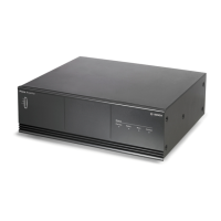
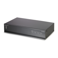
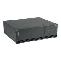
The Plena Booster Amplifier series, including models LBB 1930, LBB 1935, and LBB 1938, are mono amplifiers designed for public address and sound reinforcement systems. They offer robust performance with various output power options and comprehensive protection features, making them suitable for diverse applications.
These booster amplifiers are designed to amplify audio signals for distribution to loudspeakers. They feature constant voltage outputs (70 V and 100 V) for long-distance speaker lines and a low impedance output (8 Ohm) for direct speaker connections. The LBB 1938 model further enhances functionality with double inputs, a priority function, and priority-controlled outputs, allowing for more complex multi-zone sound systems and emergency override capabilities. All models are protected against overload and short circuits, ensuring reliable operation. A temperature-controlled fan and overheat protection mechanism are built-in to maintain optimal operating conditions and prevent damage. The amplifiers also support battery operation with automatic switchover from the mains supply, providing an uninterrupted power supply for critical applications. Balanced line inputs with loopthrough facilities allow for easy integration into existing audio setups and daisy-chaining multiple amplifiers. A 100 V slave input is also available for connecting to existing 100 V loudspeaker lines, enabling additional output power from remote locations.