Do you have a question about the Bosch LTC 5136/61 and is the answer not in the manual?
Covers instructions, warnings, handling, water, accessories, and ventilation guidelines.
Addresses power sources, grounding, cord protection, overloading, and servicing requirements.
Details service requirements, replacement parts, grounding, and lightning protection.
Outlines FCC compliance rules, conditions, and potential interference in residential areas.
Warning against opening the unit to avoid electric shock; refer servicing to qualified personnel.
Explains lightning flash (dangerous voltage) and exclamation point (important instructions) symbols.
Installation requires qualified personnel; power disconnect is via the power cord.
Check for all items listed after unpacking.
Notify shipper or service if items are damaged; save carton.
Contact nearest service center for repair authorization and shipping.
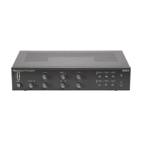
LTC 5136 Series controllers for AutoDome/Allegiant cameras, supporting various functions.
Biphase control code cable can extend up to 1.5 km using shielded twisted pair.
Model number and operating voltage are shown on the product label.
Install controller conveniently, connect power/data via interface unit.
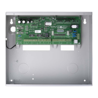
Connect interface unit, power supply, and biphase cables for camera control.
Connect controller directly to cameras/drivers via RS-232, interface unit not used.
Use LTC 8557 junction box for RS-232 connections; wire TX and Signal Ground.
Connect RS-232 data via transmission link, convert to biphase using interface unit at camera site.
Install interface unit, connect power, and use appropriate cable for biphase outputs.
Connect data cable and set address for camera/driver, or use Fast Address feature.
Set AutoDome addresses via controller/menu instead of thumbwheel.
Step-by-step guide to set or clear Fast Address for cameras.
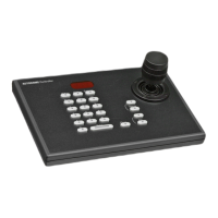
Select camera using keypad, then operate using joystick and lens controls.
LED display shows data/camera number; SET key programs pre-positions.
USER key enters diagnostic mode for checking LEDs and calibrating joystick.
CAMERA key for selection/correction; Numeric keypad for entry.
SHOT, ON, OFF keys for pre-positions and auxiliary functions.
ENTER key to terminate, CLEAR key to reset entries.
FOCUS/IRIS rocker switches and Joystick for camera pan, tilt, zoom.
Diagram showing biphase control code wiring for a single camera site.
Diagram showing daisy chain wiring for multiple camera sites using biphase.
Diagram illustrating RS-232 direct connection to a camera site.
Diagram showing RS-232 link to biphase conversion for camera sites.
Details the supplied 6-conductor 3 m (10 ft) data cable.
Illustrates the connector pinouts on the rear panel of the controller.
Provides the physical mounting dimensions for the supplied interface box.
Lists pin connections for the 9-pin male data input connector.
Lists pin connections for the RJ-11 keyboard (KBD) connector.
| Type | Camera |
|---|---|
| Input Channels | 1 |
| Power Supply | 12 V DC |
| Camera Technology | IP |
| Varifocal | Yes |
| Mount Type | Ceiling/Wall |
| Sensor Type | CMOS |
| Minimum Illumination | 0.1 Lux |
| Signal-to-Noise Ratio | >50 dB |
| Video Output | BNC |
| Weight | 0.5 kg |
| Network Interface | Ethernet |
| Image Sensor | 1/3" CMOS |
| Video Compression | H.264, MJPEG |