Do you have a question about the Bosch Plena LBB1956/00 and is the answer not in the manual?
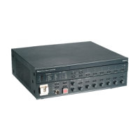
Provides an overview of the front panel controls, connections, and indicators on the voice alarm controller.
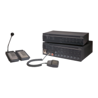
Details the controls, indicators, and connectors on the call station, including power, zone selection, and PTT button.
Describes how to install a basic Plena Voice Alarm System.
Outlines checks for environmental, electrical, and physical requirements at the installation site.
Explains suitability for table-top and 19-inch rack-mounting, and ventilation requirements.
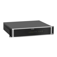
Describes connecting an external power amplifier using XLR and screw terminals based on channel mode.
Details the 6 zone outputs and 2 redundant lines per zone for connecting loudspeakers.
Details steps for connecting to mains power, including voltage selection and fuse type.
Explains connecting a 24 V(DC) back-up power supply to the voice alarm controller.
Explains that configuration uses DIP switches on the voice alarm controller and call station.
Details how to configure system settings using DIP switches on the rear of the voice alarm controller.
Covers supervision of loudspeaker lines, including short-circuit, impedance, and short-to-ground.
Details how to turn on the voice alarm controller using the Power switch.
Explains how to turn off the voice alarm controller using the Power switch.
Describes the necessity and procedure for calibrating loudspeaker line impedance supervision.
Details pushing the emergency button on the voice alarm controller to enter the emergency state.
Explains acknowledging the emergency state with the EMG Ack button to silence the beeper.
Describes resetting the emergency state by pushing the EMG Reset button after acknowledgment.
Guides on selecting zones and making announcements using the emergency microphone.
Guides on selecting zones and starting the default alert message.
Explains distributing the default alarm message, similar to the alert message.
Details acknowledging the fault state with the Fault Ack button to silence the beeper.
Describes resetting the fault state by pushing the Fault Reset button after acknowledgment.
Explains system and loudspeaker line fault indicators and their meanings.
| Number of Zones | 6 |
|---|---|
| S/N (flat at max. volume) | >70 dB |
| Mains Voltage | 100-240V AC, 50/60Hz |
| Battery Voltage | 24V DC |
| Distortion | <1% (at rated output) |
| Loudspeaker Outputs | 6 zones, 100V line |
| Operating Temperature | +45°C |
| Storage Temperature | +70°C |
| Mounting | 19" rack |
| Audio Outputs | headphone output |
| Amplifier Outputs | 6 x Zone outputs (100V) |
| Signal-to-Noise Ratio | >70dB |
| Total Harmonic Distortion | <1% |
