EN | 84 Bosch Security Systems | December 13, 2005
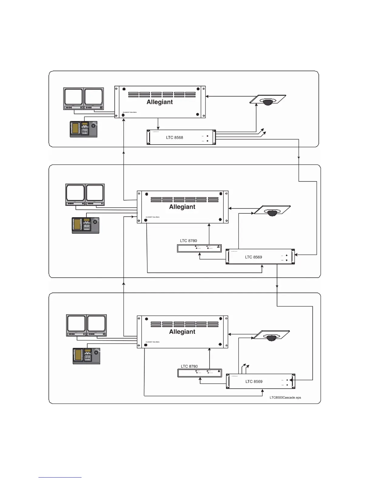
Conceptual Diagram of Cascaded Allegiant Satellite System
Figure 19: Conceptual Diagram of Cascaded Allegiant Satellite System
Typical IntuiKey
Keyboard
Typical IntuiKey
Keyboard
Typical IntuiKey Keyboard
Typical System Monitors
(Video from Local Site Only)
Multiple Video
Trunk Lines
Biphase Data Line to
3rd Level Satellite
Typical Biphase Data Line
to all Local P/T/Z Cameras
Typical P/T/Z Camera
Typical Allegiant Satellite, Site 3
Biphase
Data
Console
Port
Biphase
Data
Video
Video
Console
Port
Biphase
Data
Biphase
Data
Biphase
Data
Video
Code Merger Unit
Data
Converter
Unit
Data
Converter
Unit
Typical Biphase Data Line
to all Local P/T/Z Cameras
Typical P/T/Z Camera
Typical System Monitors
(Video from Sites 2 and 3)
Typical System Monitors
(Video from all Sites)
Typical Allegiant ‘Primary’ Master Site 1
Typical Biphase Data
Line to all Local
P/T/Z Cameras
Signal Distribution Unit
1 or More Video
Trunk Lines
Biphase Data Line to
Intermediate Master / Satellite
Typical Allegiant ‘Intermediate’ Master / Satellite, Site 2
Typical P/T/Z Camera
Code
Merger
Unit
 Loading...