Error handling instructions for Split outdoor unit
Split ODU – 6 720 817 722 (2015/06)
17
2.7 Error code 27
2.7.1 Error diagnosis and countermeasure flow chart
PFCM module checking method
1. Set the multi tester to diode mode
2. Check short circuit between input signal pins which are placed below
PFC module
3. Replace PCB assembly 1 if it is short circuit between pins except
number 4, 5 pins.
Display
code
Title Cause of error
Check point & Normal
condition
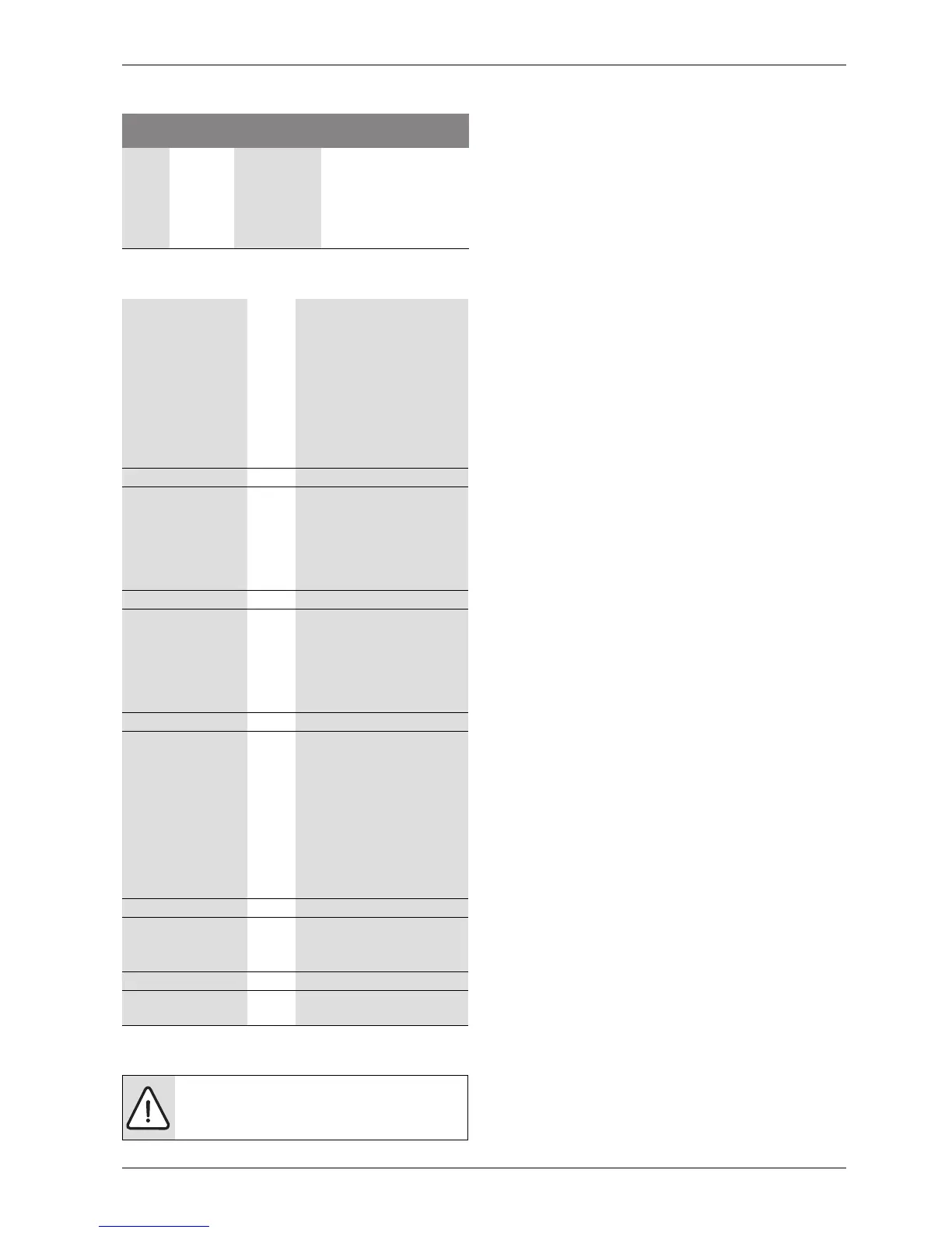
27 DC
compressor
position
• Compressor
starting
failure
1. Check the connection of
comp wire “U,V,W”
2. Malfunction of
compressor
3. Check the component of
“IPM”, detection parts
Table 13 Error code 27
Is installation condition
normal?
No -> 1. Check pipe clogging /
distortion
2. Check covering (Indoor /
Outdoor unit)
3. Check EEV connector
assembly condition / normal
operation
4. Check refrigerant pressure
-->Reassemble or manage if
abnormality found
Yes
Is input voltage normal? No -> 1. Check that L-N phase voltage is
230 15% (1~)
2. Check that R-S-T-N phase
voltage is 380 15% (3~)
--> Check connection condition
and wiring if power is abnormal
Yes
Is AC input wire
connection condition
normal?
No -> 1. Check L-N connection
condition
2. Check wire disconnection and
wiring
--> Reassemble if abnormality
found
Yes
Is compressor wire
connection condition
normal?
No -> 1. Check PCB assembly U,V,W
connector connection
condition
2. Check wire disconnection and
wiring
3. Check compressor terminal
connection condition (bad
contact)
--> Reassemble if abnormality is
found
Yes
Is PCB assembly 1
normal?
No -> 1. Check PCB assembly 1 PFCM
normality
--> Replace PCB assembly 1
Yes
Recheck power and
installation condition
Table 14 Error diagnosis and countermeasure chart
CAUTION: PFCM module number 4 and 5 pins are
internal short state.