Error handling instructions for Split outdoor unit
Split ODU – 6 720 817 722 (2015/06)
23
2.11 Error code 41, 44, 45, 46, 48
2.11.1 Error diagnosis and countermeasure flow chart
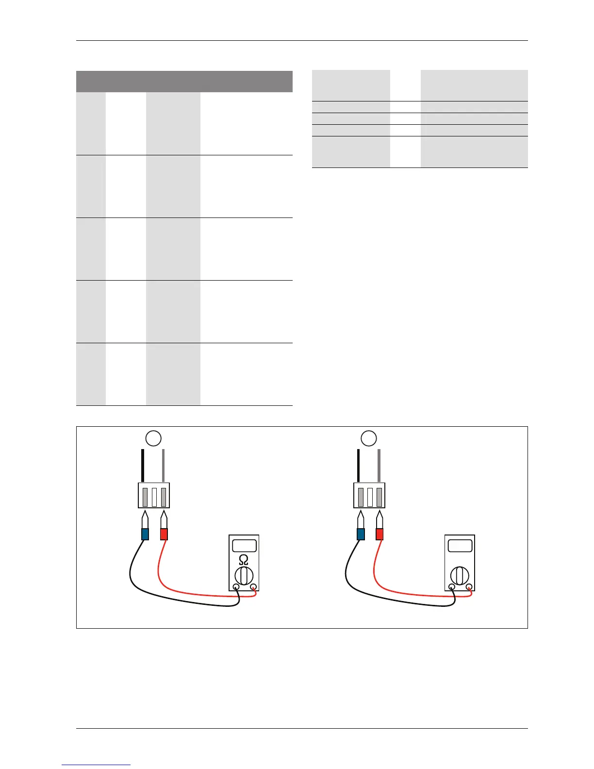
Fig. 20 Check sensor
[1] Unplugged; check the resistance (10k)
[2] Plugged; check the voltage (2.5V DC)
Display
code
Title Cause of error
Check point & Normal
condition
41 D-pipe
sensor
(inverter)
• Open / short
• Soldered
poorly
• Internal
circuit error
1. Bad connection of
thermistor connector
2. Defect of thermistor
connector (open / short)
3. Defect of outdoor PCB
(inverter)
44 Air sensor • Open / short
• Soldered
poorly
• Internal
circuit error
1. Bad connection of
thermistor connector
2. Defect of thermistor
connector (open / short)
3. Defect of outdoor PCB
(inverter)
45 Condenser
Mid-pipe
sensor
• Open / short
• Soldered
poorly
• Internal
circuit error
1. Bad connection of
thermistor connector
2. Defect of thermistor
connector (open / short)
3. Defect of outdoor PCB
(inverter)
46 Suction
pipe sensor
• Open / short
• Soldered
poorly
• Internal
circuit error
1. Bad connection of
thermistor connector
2. Defect of thermistor
connector (open / short)
3. Defect of outdoor PCB
(inverter)
48 Condenser
out-pipe
sensor
• Open / short
• Soldered
poorly
• Internal
circuit error
1. Bad connection of
thermistor connector
2. Defect of thermistor
connector (open / short)
3. Defect of outdoor PCB
(inverter)
Table 21 Error code 35
Is sensor connected to
PCB (inverter)
correctly?
No -> 1. Connect sensor to PCB
(inverter) correctly
Yes
Is sensor value correct? No -> 1. Replace sensor
Yes
• Replace
corresponding PCB
(inverter)
Table 22 Error diagnosis and countermeasure chart
V
6 720 817 722-18.1I
1 2