English | 27
Bosch Power Tools 1 609 92A 27V | (8.3.16)
58 Quick release of quick-action clamp
59 Locking knob of the quick-action clamp
60 Wing bolt of the quick-action clamp
61 Supporting bar of the quick-action clamp
62 Mounting holes for horizontal fixing
63 Saw-table extension (flexible)
64 Opening for flexible saw-table extension 63
(on the power tool)
65 Opening for flexible saw-table extension 63
(on the stationary saw-table extension 12)
66 Fastening screw for insert plate
Accessories shown or described are not part of the standard deliv-
ery scope of the product. A complete overview of accessories can
be found in our accessories program.
Technical Data
Noise Information
Sound emission values determined according to
EN 62841-3-9.
Typically the A-weighted noise levels of the product are:
Sound pressure level 93 dB(A); Sound power level
106 dB(A). Uncertainty K =3 dB.
Wear hearing protection!
Assembly
Avoid unintentional starting of the machine. During as-
sembly and for all work on the machine, the power plug
must not be connected to the mains supply.
Delivery Scope
Please also observe the representation of the
delivery scope at the beginning of the operat-
ing instructions.
Before starting the operation of the machine
for the first time, check if all parts listed be-
low have been supplied:
– Sliding mitre saw with mounted saw blade
–Dust bag 53
– Stationary saw-table extension 12 (2 x),
Fastening screws 51 (2 x)
– flexible saw-table extension 63 (2 x)
– Quick-action clamp 22
–Hex key 49
Note: Check the power tool for possible damage.
Before further use of the machine, check that all protective
devices are fully functional. Any lightly damaged parts must
be carefully checked to ensure flawless operation of the tool.
All parts must be properly mounted and all conditions fulfilled
that ensure faultless operation.
Damaged protective devices and parts must be immediately
replaced by an authorised service centre.
Mounting Individual Components
– Carefully remove all parts included in the delivery from
their packaging.
– Remove all packaging material from the machine and the
accessories provided.
Mounting stationary saw-table extensions (see figure A)
The stationary saw-table extensions 12 with the fastening
screws 51 must be screwed to the left and right of the saw ta-
ble 21 with the power tool.
– Tilt the saw-table extension 12 backward slightly and place
it in the groove of the opening 52 on the power tool, turn
the saw-table extension forward horizontally in the groove
and then press the saw-table extension fully downward.
– Tighten the fastening screws 51 with the hex key 49 pro-
vided.
Stationary or Flexible Mounting
Mounting to a Working Surface (see figure B)
– Fasten the power tool with suitable screw fasteners to the
working surface. The mounting holes 20 serve for this pur-
pose.
Flexible Mounting (not recommended!) (see figure C)
In exceptional cases, when it is not possible to mount the ma-
chine onto a level and stable work surface, it can be set up us-
ing the tilt protector.
Without the use of the tilt protector, the machine does
not stand safely and can tip over, especially when saw-
ing at maximum mitre/bevel angles.
– Screw the tilt protector 15 in or out until the machine is po-
sitioned level on the working surface.
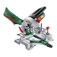
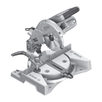
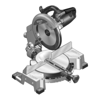
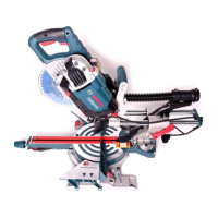
Sliding Mitre Saw PCM 8 SD
Article number
3603M110..
Rated power input
W 1200
No-load speed
min
-1
4800
Laser type
nm
mW
650
<1
Laser class
2
Weight according to
EPTA-Procedure 01:2014 kg 15.5
Protection class
/II
Permissible workpiece dimensions (maximum/minimum) see page 30.
The values given are valid for a nominal voltage [U] of 230 V. For differ-
ent voltages and models for specific countries, these values can vary.
Dimension of suitable saw blades
Saw blade diameter
mm 216
Blade body thickness
mm 1.4–1.8
Max. cutting width
mm 2
Mounting hole diameter
mm 30
OBJ_BUCH-2765-001.book Page 27 Tuesday, March 8, 2016 9:56 AM