Do you have a question about the Bosch GCM 8 SJ and is the answer not in the manual?
Read all safety warnings and instructions. Failure to follow may result in electric shock, fire or serious injury.
Keep work area clean and well lit. Do not operate in explosive atmospheres. Keep children and bystanders away.
Power tool plugs must match the outlet. Avoid body contact with earthed surfaces. Do not expose to rain or wet conditions.
Stay alert, watch what you are doing. Use protective equipment. Prevent unintentional starting. Do not overreach. Dress properly.
Do not force the power tool. Use the correct tool. Do not use if switch is faulty. Disconnect plug before adjustments. Store idle tools out of reach.
Have your power tool serviced by a qualified repair person using only identical replacement parts.
Do not stare into laser beam. Keep hands away from cutting area. Keep handles dry, clean, and free from oil.
Operate tool only when work area is clear. Firmly clamp workpiece. Use machine only for intended use. If blade jams, switch off.
Do not direct laser beam at persons or animals. Laser class 2 product.
Wear dust respirator, safety goggles, and ear protectors for safety.
Observe saw blade dimensions. Hole diameter must match spindle. Do not use reducers or adapters.
Do not dispose of power tools into household waste. Collect separately for environmentally correct disposal.
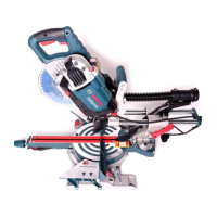
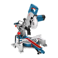
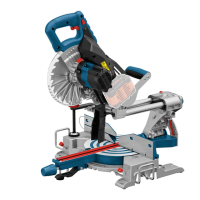
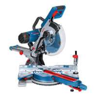
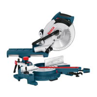
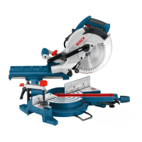
Stationary machine for straight lengthways and crossways cuts in wood, particle and fibre board. Mitre angles -50° to +58°, bevel angles 0° to 45°.
Description of components numbered 1-59, referring to graphic pages for identification and function.
Technical specifications for the GCM 8 SJ Professional, including power, voltage, speed, laser type, weight, and protection class.
Specifications for suitable saw blades: diameter, thickness, and mounting hole diameter.
Details A-weighted noise levels and vibration emission values determined according to EN 61029.
Declaration of sole responsibility for product conformity with EN 61029, EN 60825-1 and EU directives.
Avoid unintentional starting of the machine. Ensure power plug is disconnected before assembly or maintenance.
Check if all listed parts are supplied before first operation. Inspect tool for possible damage.
Mount machine securely to a workbench using screws or clamps. Ensure stability for safe operation.
Use Bosch GTA saw stands for stable support. Follow worktable instructions. Mount tool in transport position.
Use tilt protector for setup on uneven surfaces. Machine may tip over without it, especially at maximum angles.
Use dust extraction whenever possible. Ensure good ventilation. Wear a P2 filter-class respirator. Observe country regulations.
Use dust bag for basic collection. Clean bag after use. Remove bag when sawing aluminum to avoid fire risk.
Connect a vacuum hose (Ø 36 mm) to the dust ejector 22. Use a vacuum cleaner suitable for the material.
Disconnect mains plug before work. Wear protective gloves when mounting blade. Use recommended blades.
Release locking lever, loosen screw, press spindle lock, unscrew Allen screw, remove flange and blade.
Clean parts. Place new blade on flange. Align teeth direction with arrow. Secure with flange and screw. Fasten guard.
Pull On/Off switch 4 in direction of handle 5. Switch cannot be locked; must be pressed during operation.
Transport safety-lock 27 enables easier handling when transporting to various working locations.
Push tool arm down slightly to relieve lock. Pull lock outward completely. Guide arm upward.
Loosen locking screw 25. Pull arm forward completely and retighten screw. Screw depth stop up. Tighten locking knob 11.
Ensure workpiece is firmly clamped. Do not saw workpieces too small to clamp. Use material clamp 42.
Check and adjust basic adjustment after intensive use. Tighten locking knob 11 firmly before sawing.
Set angle from -50° to +58°. Loosen locking knob 11. Use lever 12 and detents 14 for setting.
Set angle from 0° to 45°. Loosen clamping lever 21. Use angle indicator 20. End stops provided for 0° and 45°.
Pull On/Off switch 4. Locking lever 35 must be pushed for sawing.
Release the On/Off switch 4 to stop the machine.
Electronic feature limits power consumption on startup. If failed, send tool for service.
Ensure blade clearance. Protect blade. Do not saw warped workpieces. Support long workpieces. Extend table if needed.
Laser beam indicates cutting line for precise positioning. Align workpiece with right edge of laser line. Check laser alignment.
Do not stand in line with the saw blade. Stand aside. Keep hands away from blade. Do not cross arms.
Table showing maximum and minimum workpiece sizes for various mitre and bevel angles.
Profile strips/mouldings can be sawn placed against fence or lying flat on saw table. Use slide movement based on width.
Table provides instructions for sawing floor strips/mouldings, detailing workpiece positioning and angles.
Table provides instructions for sawing ceiling strips/mouldings, specifying mitre angles 31.6° (horizontal) and 33.9° (vertical).
Adjust laser beam for accurate cutting line. Includes checking parallelism, flush leveling, and lateral deviation.
Check and adjust horizontal angle indicator alignment with the 0° mark on the scale.
Check and adjust vertical angle indicator alignment with the 0° and 45° marks on the scale.
Check fence alignment using an angle gauge. Adjust fence position to ensure it is flush with the saw blade.
Check and adjust the 0° vertical bevel angle. Ensure leg of angle gauge is flush with the saw blade.
Check and adjust the 45° vertical bevel angle. Ensure leg of angle gauge is flush with the saw blade.
Follow steps to secure machine for transport: loosen locking screw, screw depth stop up, bring to transport position, remove accessories.
Disconnect mains plug before work. Keep tool and ventilation slots clean. Ensure blade guard moves freely.
Keep tool and ventilation slots clean. Ensure retracting blade guard moves freely. Blow out dust and chips. Clean roller and lighting/laser unit.
Contact after-sales service for maintenance, repair, and spare parts. Visit www.bosch-pt.com for information.
List of available accessories with part numbers, including dust bag, material clamp, extension bars, insert plates, and saw blades.
Sort machine, accessories, and packaging for recycling. Plastic components are labelled for recycling. EC countries: Do not dispose of in household waste.
| Type | Sliding Mitre Saw |
|---|---|
| Blade Diameter | 216 mm |
| Cutting Capacity, 0° | 70 x 312 mm |
| Saw Blade Bore Diameter | 30 mm |
| Max Cutting Depth at 90° | 70 mm |