40 | English
1 609 929 W28 | (16/4/10) Bosch Power Tools
External Dust Extraction
For dust extraction, a vacuum hose (size
Ø 36 mm) can also be connected to the dust
ejector 22.
– Connect the vacuum hose with the sawdust
ejector 22.
The vacuum cleaner must be suitable for the ma-
terial being worked.
When vacuuming dry dust that is especially det-
rimental to health or carcinogenic, use a special
vacuum cleaner.
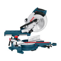
Changing the Tool (see figures D1– D4)
f Before any work on the machine itself, pull
the mains plug.
f When mounting the saw blade, wear protec-
tive gloves. Danger of injury when touching
the saw blade.
Use only saw blades recommended by the tool
manufacturer, and suitable for sawing the mate-
rials to be cut.
Use only saw blades whose maximum permitted
speed is higher than the no-load speed of the
power tool.
Use only saw blades that correspond with the
characteristic data given in these operation in-
structions and that are tested and marked in ac-
cordance with EN 847-1.
Removing the Saw Blade
– Push the locking lever 35 and swing the re-
tracting blade guard 6 to the rear to the stop.
– Loosen the screw 36 with the Phillips screw-
driver 26 provided until the fastening ele-
ment of the retracting blade guard can also
be swung to the rear to the stop.
– Turn the Allen screw 38 with the Allen key 26
provided while at the same time pressing the
spindle lock 37 until it engages.
– Hold the spindle lock 37 pressed and un-
screw the Allen screw 38 in clockwise direc-
tion (left-hand thread!).
– Remove the clamping flange 39.
– Remove the saw blade 40.
Mounting the Saw Blade
If required, clean all parts to be mounted prior
to assembly.
– Place the new saw blade onto the interior
clamping flange 41.
f When mounting the saw blade, pay atten-
tion that the cutting direction of the teeth
(arrow direction on the saw blade) corre-
sponds with the direction of the arrow on
the blade guard!
– Place on the clamping flange 39 and the Allen
screw 38. Press the spindle lock 37 until it
engages and tighten the Allen screw turning
in anticlockwise direction.
– Fasten the retracting blade guard 6 again
(tighten screw 36).
– Push the locking lever 35 and guide the re-
tracting blade guard 6 down again.
Operation
f Before any work on the machine itself, pull
the mains plug.
Transport Safety (see figure E)
The transport safety-lock 27 enables easier han-
dling of the machine when transporting to vari-
ous working locations.
Releasing the Machine (Working Position)
– Push the tool arm by the handle 5 down a lit-
tle in order to relieve the transport safety-
lock 27.
– Pull the transport safety-lock 27 completely
outward.
– Guide the tool arm slowly upward.
Securing the Machine (Transport Position)
– Loosen the locking screw 25 if tightened.
Pull the tool arm completely to the front and
tighten the locking screw again.
– Screw the depth stop 23 completely to the
top. (see “Adjusting the Depth Stop”,
page 43)
– To lock the saw table 8, tighten the locking
knob 11.
OBJ_BUCH-1168-001.book Page 40 Friday, April 16, 2010 5:25 PM
 Loading...