English | 19
Bosch Power Tools 1 609 929 W68 | (3.3.10)
Operation
Sawing
Preparing for Operation
The saw station must be assembled depending
on the respective sawing application:
– Sawing Panels
(e. g. laminate flooring panels)
– Sawing Profiles
(e. g. baseboards)
The use of screws/bolts is not required.
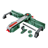
Panel (cross section) (see figures A1 – A3)
– Mount the support extensions 6 left and right
to the base unit 1.
– Depending on the workpiece size, mount the
additional supports 7 to the inner or outer
guide of the support extensions.
– Loosen the locking knob 3 a few turns.
– Turn the locking lever 10 of the guide rail left-
ward and fold the guide rail 4 upward.
– Mark the desired cutting line on the work-
piece.
– Place down the workpiece with the visible
side flat against the stop of the base unit 1.
– Fold the guide rail downward and align the
workpiece to the cutting line of mark 11.
– Lock the guide rail 4 with locking lever 10.
– Tighten the locking knob 3.
Panel (mitre cuts) (see figure B)
The horizontal mitre angle can be set in the
range from 45° (left side) to 45° (right side).
– Loosen locking knob 12.
– Turn the guide rail 4 left or right until the an-
gle indicator 13 indicates the requested mi-
tre angle.
– Tighten the locking knob 12 again.
For swift and precise adjustment of standard
mitre angles, the guide rail engages at 0° and
45°.
– For additional worksteps, see “Panel (cross
section)” on page 19.
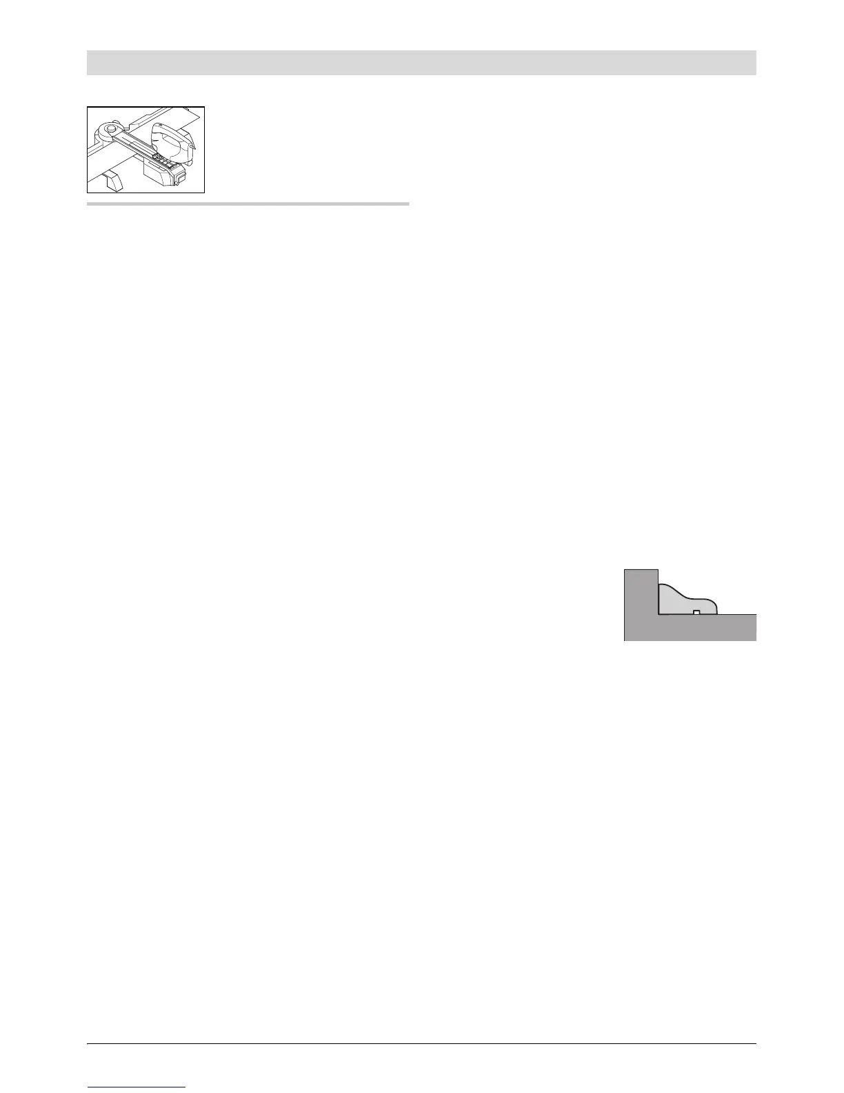
Profile (bevel cuts) (see figures C1–C3)
– Mount the support extensions 6 left and right
at the front position of the bridge 8.
– Fold the red end stop 9 by 180° to the rear.
– Loosen the locking knob 3 a few turns.
– Turn the locking lever 10 of the guide rail left-
ward and fold the guide rail 4 upward.
– Mark the desired cutting line on the work-
piece.
– Place down the
workpiece flat
against the stop of
the support exten-
sions 6.
– Fold the guide rail downward and align the
workpiece to the cutting line of mark 11.
– Lock the guide rail 4 with locking lever
10.
– Tighten the locking knob 3.
– Adjust the base plate of the jigsaw according-
ly to the desired angle.
Notes on the adjustment are given in the op-
erating instructions of the jigsaw.
Note: The folded back red end stop 9 is used as
the stop for the base plate of the power tool.
OBJ_BUCH-1219-001.book Page 19 Wednesday, March 3, 2010 9:25 AM
 Loading...