Installation | 15
6 720 805 490 (2015/06)ProControl Gateway
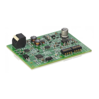
2.2 Specification
2.3 Cleaning and care
▶ If required, wipe the enclosure with a damp cloth. Never use
chemically aggressive or acidic cleaning agents.
3 Installation
3.1 Installation
▶ Remove cover ( Fig. 3, page 98).
▶ Mount the module ( Fig. 4, page 98).
▶ Secure the module ( Fig. 5, page 98).
3.2 Electrical connections
Connections and interfaces
Legend to Fig. 6 and 7, page 99:
7,5 V DC Power supply unit connection
CAN 1 Ground (GND)
CAN 2 CAN Low
CAN 3 CAN High
HT 2-wire BUS system connection
LAN LAN connection (RJ45)
RESET RESET button
TSW Switch for CAN connection
Pre-assembling the ferrules and connecting the cable
▶ Open the grommets to match the cable diameter and cut in on one
side ( Fig. 8, page 99).
▶ Fit the ferrules and connect the cables (2-wire BUS: Fig. 9,
page 99; CAN: Fig. 10, page 99).
3.3 Connecting the BUS connections
Maximum total length of the BUS connection between all subscribers
of the corresponding BUS system:
• 2-wire BUS:
– 80 m at max. 0.40 mm
2
conductor cross-section
– 100 m at max. 0.50 mm
2
conductor cross-section
– 150 m at max. 0.75 mm
2
conductor cross-section
– 200 m at max. 1.00 mm
2
conductor cross-section
– 300 m at max. 1.50 mm
2
conductor cross-section
• CAN:
– 30 m (shielded, twisted wires)
Suitable cables for the corresponding BUS system:
• 2-wire BUS: e.g. LiYCY 2 x 0.75 (TP)
• CAN: 2 × 2 × 0.3 mm
2
; shielded, twisted wires
▶ All LV leads must be routed separately from cables carrying mains
voltage to avoid inductive interference (minimum separation
100 mm).
Connecting the 2-wire BUS system to the module
▶ Connect BUS subscribers with two BUS connectors in series
( Fig. 6, page 99) or BUS subscriber [B] with one junction box [A]
in a star configuration ( Fig. 11, page 99).
▶ In case of external inductive interference, shield the cables.
This ensures that the cables are shielded from external interference
(e.g. heavy current cables, overhead wires, transformer stations,
radio and television set, amateur radio stations, microwave ovens
etc).
Connecting the CAN BUS system to the module
▶ Connect the shielding of the CAN cable in the module to CAN 1
(earth).
▶ Connect one wire of the twisted wire pair in the module to CAN 2
(CAN Low).
▶ Connect the second wire (of the twisted wire pair used for CAN 2)
inside the module to CAN 3 (CAN High) ( Fig. 7, page 99).
Make CAN connection to heat pump.
▶ Find free CAN connections in the heat pump.
▶ If no free connection is available in the heat pump, the CAN cable
must be connected sharing the connection with another accessory.
Specifications
Dimensions (W × H × D) 151 × 184 × 61 mm (further
dimensions Fig. 2, page 98)
Rated voltages:
• BUS system
• CAN BUS system
• Module power supply
• 12 V to 15 V DC (reverse polarity
protected)
• 0V to 5V
• Plug power supply unit supplied
230 V AC/7.5 V DC, 700 mA
Interfaces • 2-wire BUS
• CAN
• LAN: 10/100 MBit/s (RJ45)
Power consumption 1.5 VA
Permissible ambient
temperature
0 ... 50 °C
Protection class IP20
Table 11
If the maximum total length of the BUS connections
between all subscribers in a BUS system is exceeded,
the system cannot be commissioned.
If a ring structure is present in the 2-wire BUS system,
the system cannot be commissioned.
Verify the correct position of the two CAN connection
switches to ensure that the CAN system is correctly
connected ( Fig. 7, page 99).
▶ If the module is an end point, both switches must be
set to ON.
▶ If the module is connected to a branch line, both
switches must be set to OFF.