B A
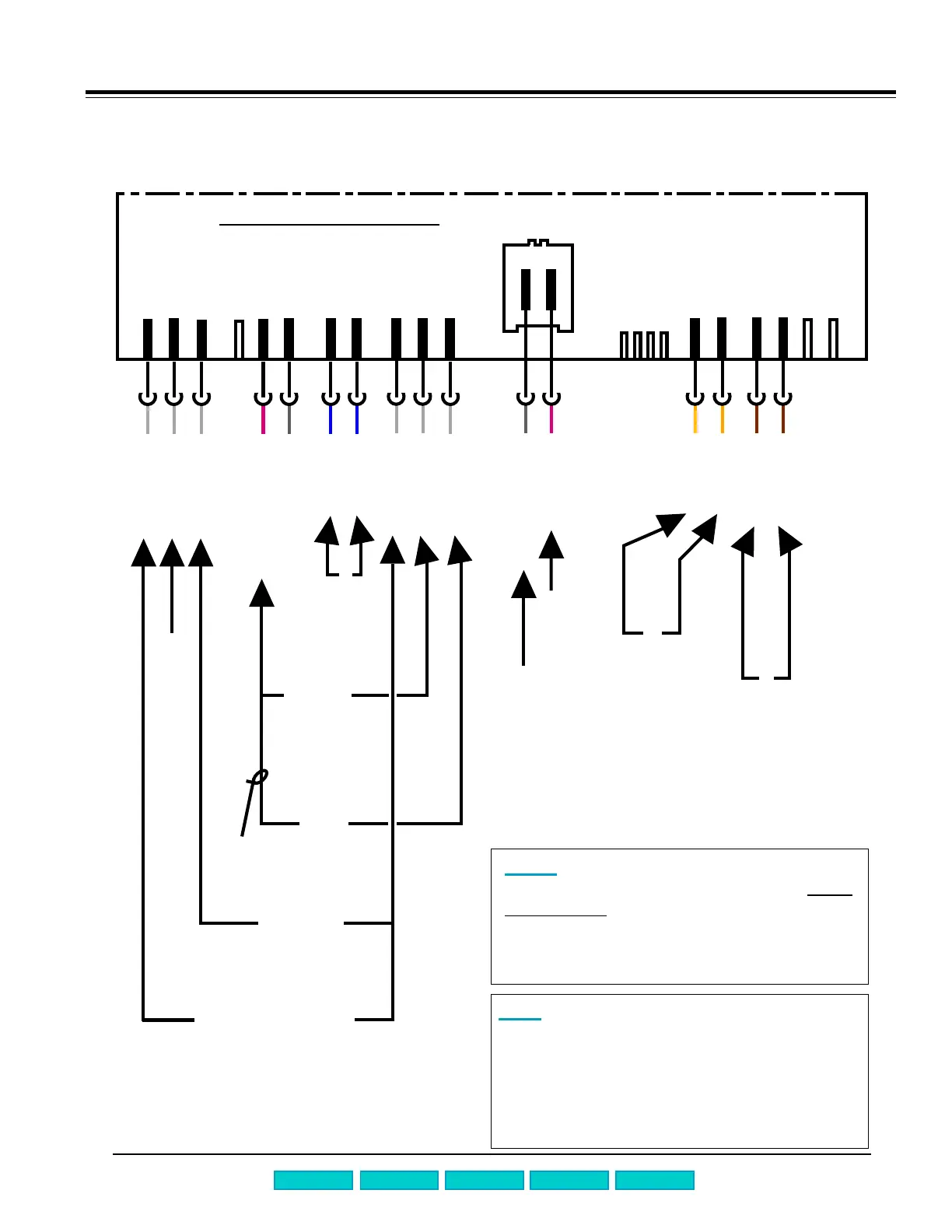
Measuring resistances from the front
of SHU 99 & SHV 43/48 dishwashers
Page A-2
WHRD-e0-1
GY-e0-4
WH-I6-4
WH-I6-5
WH-I6-6
WH-I6-9
WH-I6-8
WH-I6-7
BU-A2
BU-A2
YE-e3
YE-e3
BN-I6-3
BN-I6-2
GYBK-a1-3
RD-I6-1
measure
NTC
(~ 55 kW
@ 72ºF)
measure
rinse agent
sensor
(SHV 48)
(~.4 W)
measure water
level switch
(open circuit)
measure top rack only
actuator (SHV 48 only)
(~2150 W)
measure
dispenser
actuator
(~2150 W)
measure
drain
motor
(~16.5 W)
measure
circulation
motor (with
door closed)
(~10 W)
to hot line
to water valve & float switch
HINT: Water valve and drain motor can be
measured from front of dishwasher without
accessing control module wire harnesses.
Resistances are:
n Water valve ~ 1 kW
n Drain motor ~ 16.5 W
NOTE: Symbols (WH-I6-7) refer to wire
colors and terminal/part symbols. See
circuit
diagram # 48 for terminal/part symbols. Wire
colors: WH = white, WHRD = white/red, GY =
gray, BU = blue, GYBK = gray/black, RD = red,
YE = yellow, BN = brown.
to heater, Hi-Limit & flow switch
to
neutral
Control Module -- I2
.1
.2 .3
.6
.7
.5
.4 .8
2
12431
21
231
2113
2
213
I2.
1st Edition/Revision 2 Tuesday, August 8, 2000
Tech Manual
TroubleshootingQuick Chart
Test Programs
Repair Manual