B A
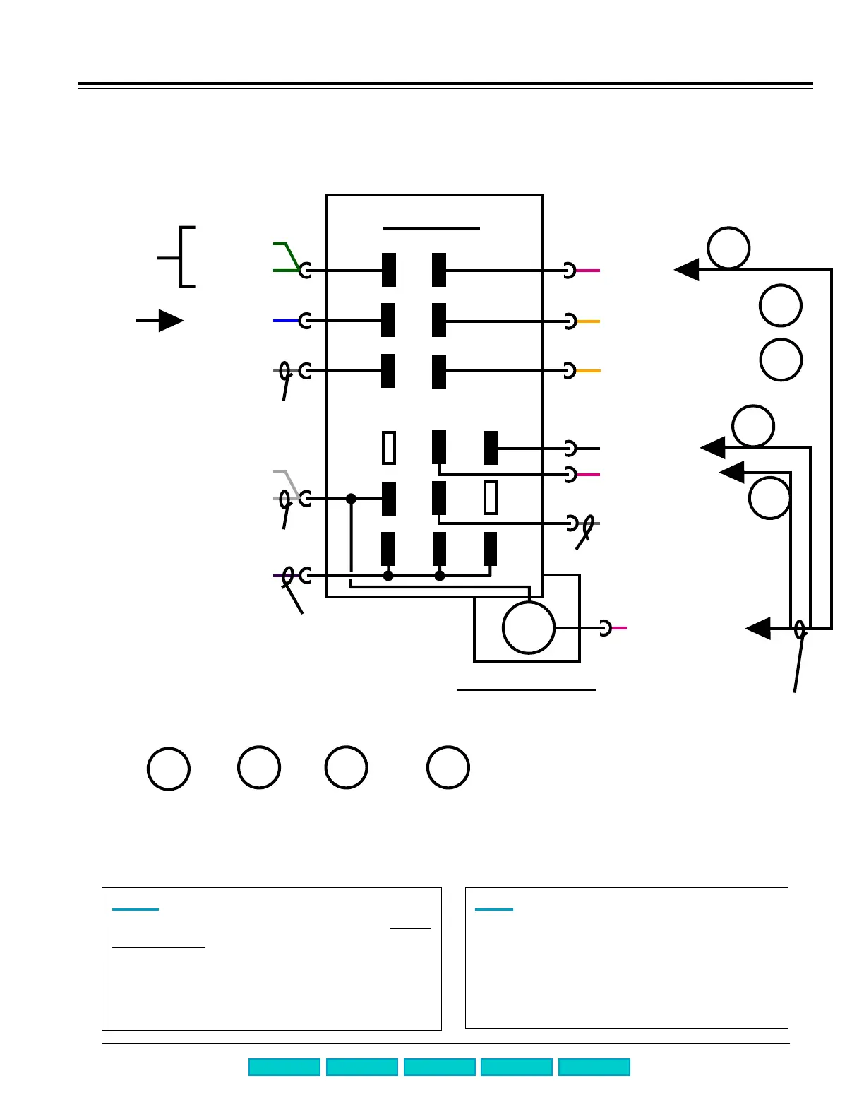
Measuring resistances from the front
of SHU 303x dishwashers
Page A-4
to water level
switch & inlet
valve
M
1
~
to neutral
WHRD-A2
5b
Timer -- u
Timer motor m1
5a
5
3b
3a
3
6b
6a
6
4b
4a
4
2b
2a
2
to hot line
GYBK-e5-1
GYRD-I6-8
BK-m2-1
VT-b-3 (to b3)
YE-b-1 (to b1)
RD-A2
GN-I6-6
GN-f3
BU-I6-4
GY-I6-1
WH-b-5
WH-I6-3
NOTE: Symbols (WH-I6-3) refer to wire
colors and terminal/part symbols. See
circuit
diagram # 62 for terminal/part symbols. Wire
colors: WH = white, WHRD = white/red, WHVT
= white/violet, BU = blue, GYBK = gray/black,
BK = black, GYRD = gray/red, GY = gray, GN =
green, RD = red, VT = violet, YE = yellow.
HINT: Water valve and drain motor can
be measured from front of dishwasher
without accessing timer wire harnesses.
Resistances are:
n Water valve ~ 1 kW
n Drain motor ~ 16.5 W
to flow switch
m2
m3
1
1
A2
to thermostats
f3 & f4
to float switch
to flow switch
WHVT-a1-3
1st Edition/Revision 1 Tuesday, August 8, 2000
Tech Manual
TroubleshootingQuick Chart
Repair Manual
measure
circulation
motor
(~10 W)
m2
measure
drain
motor
(~16.5 W)
m3
1
see circuit /
schematic
diagram # 62
for b1 & b3
measure
detergent
actuator
(~2150 W)
A2