Copyright © 2018 — In the interest of ongoing product improvement we reserve the right to change specifications at any time without notice — E&OE 10/18
Problem
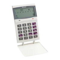
• The screen is
black
Situation
Solution
Check that the PWR LED is illuminated on the back
1. Remove the TouchOne from the wall mount. Be
careful when pulling the TouchOne away from the wall
not to stress the attached cable.
2. Look down the back of the enclosure for the Red
solid LED
• Ensure the Four pin connector is properly connected
to the back of the Touch One Screen
• Ensure the Black, Red, Green and Yellow wires are
wired in the correct order on the Bosch Alarm Panel
• The Power LED on the back of the Touch One Screen
should be a solid red color.
• The alive LED on the back of the Touch One should be
flashing at a regular interval
• It will be helpful to use a short wire and connect the
Touch One directly to the Bosch Alarm Panel. Check
the PWR LED is on and that the Alive LED is flashing.
If this test is successful, the problem may be with the
wire run between the Alarm Panel and the Touch One
Screen
• If the TouchOne powers up follow wifi update step
12. If not follow step 11.
• The
TouchOne
displays a
black screen
and does not
turn on
15 15 15
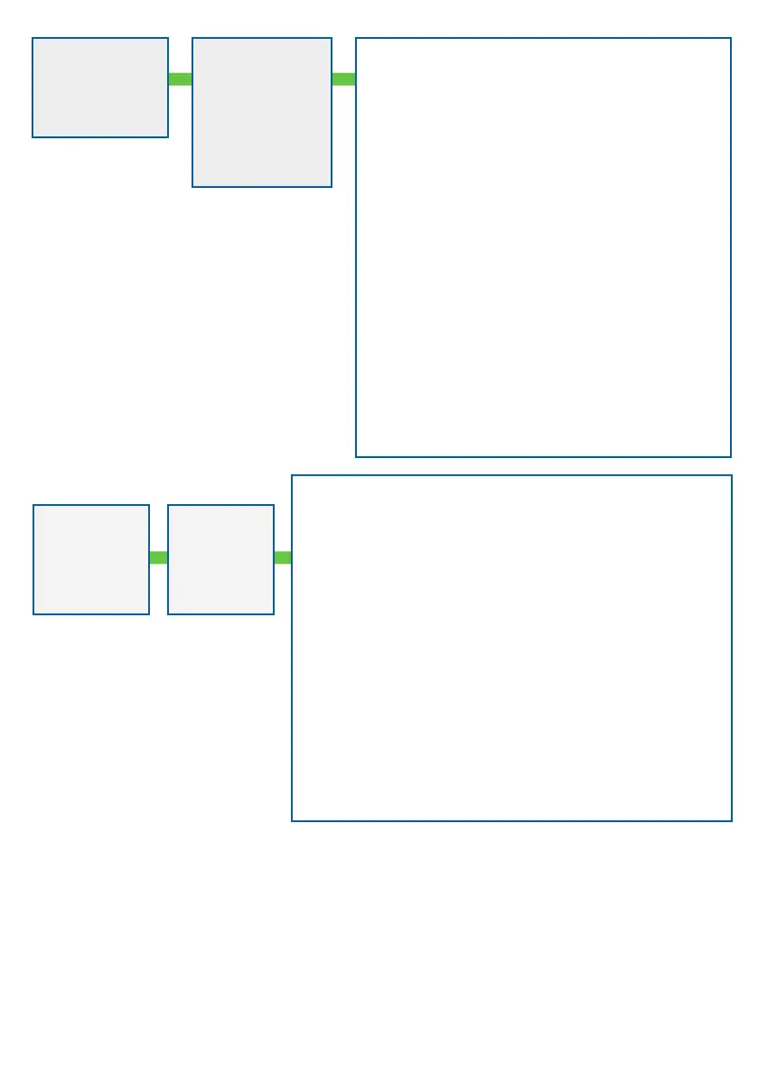
Problem Action
• Install
external
power
supplies
• 12V DC
1500mA
Power
Adapter
• When installing more than one TouchOne, all TouchOne’s except
one must be powered with external power supplies.
• The red wire from the Wire Harness connects to the positive
terminal. You will need to cut a piece of 0.5mm wire to connect
from the negative terminal to the COM terminal on the control
panel. The black wire from the Wire Harness will also need to go to
the COM terminal. The rest of the wiring is as per the original.
• Before powering up the TouchOne running off of the external
power supply, you will need to set up the areas in the control
panel, then address the TouchOne’s and/or keypad as required.
(Refer to wiring diagram from Solution 1)
Note: SDI-2 BUS only provides 900mA. Touchscreens need 800mA
• Keypads need 800 mA
• B810 needs 105mA
• B426-M/ B450-M needs 105mA
Each touchscreen needs its own power supply if in addition to any
of the above
Solution
16
16
16