SSB 6720866940 (2017/11) US
Main components | 9
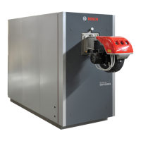
4.5 Low Water Cut Off (LWCO)
The Low Water Cut off (LWCO) is installed on the supply pipe, at the
highest position available. Using a dedicated wet sensor it checks the
minimum level of water inside the boiler by way of an electrical signal
ground. The electronic control board is located in the primary electrical
enclosure. It includes a self-test and a manual reset button (Fig. 9) To
check the functionality of LWCO, press the test button. The LED turns ON
and the boiler will display the error “Low water cut off”. At this point press
the red reset button located just below the Test button. The LED will turn
off and the error should clear from the boiler display.
Electronic Low Water Cut Off
Reset
Test
Led
Fig. 9 FLow Water Cut Off (LWCO)
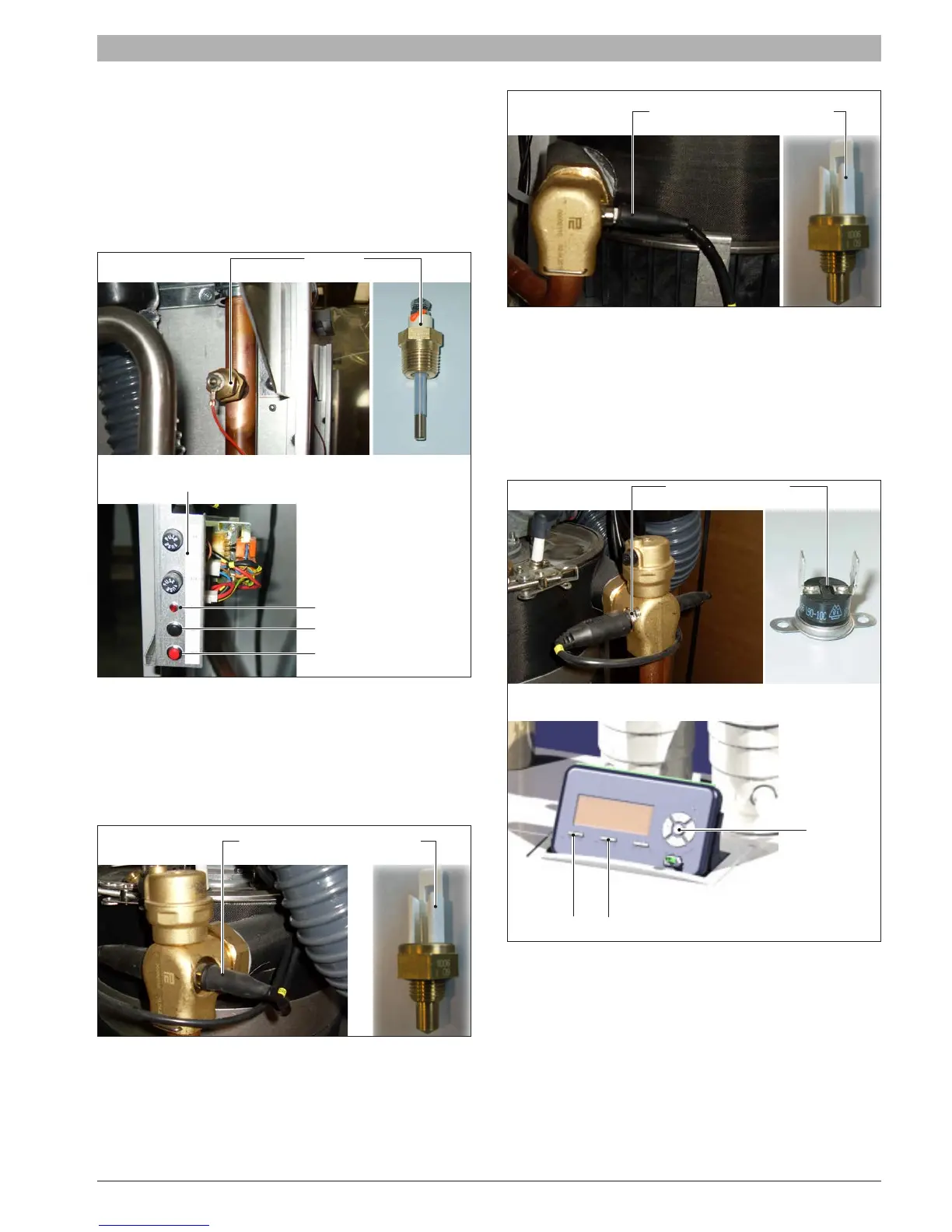
4.6 Supply and return temperature sensors
The supply (Fig. 10) and return (Fig. 11) temperature sensors are
immersion type NTC’s rated 10KΩ at 25°C(77°F).
See Tab. 12 for resistance values for NTC sensor.
The supply sensor is located at the outlet of the heat exchanger the
return temperature sensor is located at the inlet of the heat exchanger.
Supply temperature sensor
!
Fig. 10 Supply temperature sensors
Return temperature sensor
Fig. 11 Return temperature probes
4.7 Manual reset high limit
The safety thermostat (Fig. 12) is located near the supply sensor. It’s an
automatic reset type set at 194°F. Above this temperature the contact
opens removing power to the gas valve. The display shows the “over-
temperature” error code requiring manual reset. To test the functionality
of the sensor hold for 10 sec both “Ok” & “Menu” buttons on display. It will
appear the “High limit T max” error message. At this point press the reset
button to restart the boiler.
OK
Fig. 12 Manual reset High Limit Safety Thermostat