Do you have a question about the Bosch Therm 4000 S and is the answer not in the manual?
Explains warning symbols and signal words used in the manual.
Provides general safety advice for installers and users regarding operation and warnings.
Details procedures for installation, commissioning, and maintenance by approved contractors.
Outlines requirements for regular inspection and maintenance for safe operation.
Warns against unauthorized modifications and specifies contractor requirements.
Specifies that electrical work must be done by qualified electricians with safety precautions.
Discusses ventilation requirements for open flue installations.
Safety requirements for electrical devices according to EN 60335-1.
Defines the device's purpose for DHW heating and use in mobile homes.
States compliance with European directives and testing standards.
Lists different device types, gas specifications, and installation types.
Lists the items included in the product package.
Indicates the location and information found on the device's data plate.
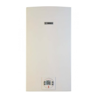
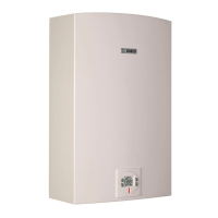
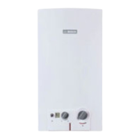
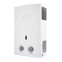
Describes the device's features, display, ignition, and safety equipment.
Lists optional accessories that are not supplied with the device.
Provides physical dimensions and required minimum clearances for installation.
Shows a diagram illustrating the internal components and their locations.
Presents the electrical schematic showing connections for various components.
Lists key technical data including output, gas, water, flue gas, and electrical specifications.
Details energy consumption data, efficiency classes, and emissions according to EU regulations.
Provides information and warnings regarding flue accessories and their installation.
Specifies maximum lengths for vertical flue systems based on pipe type.
Specifies maximum lengths for horizontal flue systems based on pipe type.
Explains the symbols and functions of the device's digital display panel.
Lists essential checks and steps required before initial operation.
Details the procedure for switching the device on and off using the power button.
Describes how to adjust and set the desired hot water temperature using the control buttons.
Explains how to save and recall preferred water outlet temperatures using the program key.
Provides instructions on how to drain the device, especially for frost protection.
Lists error codes displayed by the device and their corresponding remedies.
Advises on how to clean the exterior casing of the appliance with a damp cloth.
Provides general advice and consultation requirements prior to installation.
Guides on choosing a suitable installation location, considering general notes, type B devices, air supply, and combustion air.
Details specific regulations and country-specific requirements for the chosen installation site.
Specifies maximum and minimum lengths for flue systems based on pipe type and accessories.
Outlines the required minimum clearances around the device for installation and maintenance access.
Instructions for correctly fitting the wall mounting bracket, including preparation steps.
Step-by-step guide for physically mounting the water heater onto the wall bracket.
Details on how to properly connect the cold and hot water pipes to the device.
Instructions and safety warnings for connecting the gas supply, including different gas types.
Guidance on installing flue and air system accessories, with safety precautions.
Explains how to set the device for the specific altitude of the installation location.
Describes the procedure for the initial startup and operation of the water heater.
Instructions for making the electrical connection according to regulations, including earthing.
Steps for safely replacing a damaged power cable with original spare parts.
Notes that devices are factory-set and warns against tampering with sealed components.
How to access the service mode for advanced settings and diagnostics.
Procedure for setting the device specifically for propane gas supply.
General guide for setting device parameters, starting with P1 and P2.
Step-by-step guide to set the minimum gas volume for optimal performance.
Instructions on how to adjust burner nozzle pressure if other settings are not achievable.
Procedure to reset the device to its original factory settings for parameters.
Details on how to convert the device for a different gas type using a conversion set.
Instructions for safely removing the device's casing to access internal components.
Covers routine maintenance tasks including function checks, combustion chamber, and burner cleaning.
Explains the maintenance procedure for the water filter and flow limiter.
Steps for safely replacing the fuses located within the control device.
Procedures to follow after maintenance to ensure correct operation and safety.
Safety advice for long-term use, including visual inspections of key components.
Lists faults related to temperature sensors and casing issues, with remedies.
Covers faults related to fan, water flow rate, and air volume, with troubleshooting steps.
Details faults concerning the electronic block, overheating, and temperature sensors, with solutions.
Addresses faults like thermal fuse activation and no flame detection, with troubleshooting actions.
Lists faults for solenoid valves, gas type mismatch, and safety valve issues.
Covers faults related to key presses exceeding limits and incorrect outlet temperatures.
Addresses issues related to unusual noises or vibrations emitted by the device.
| Brand | Bosch |
|---|---|
| Model | Therm 4000 S |
| Category | Water Heater |
| Language | English |