Do you have a question about the Bosch Worcester Greenstar HIU E and is the answer not in the manual?
Explains warning symbols and their severity levels.
Provides essential safety guidelines for installation and operation.
Key points to observe when handling the appliance packaging.
Fundamental requirements for safe and economical appliance operation.
Ensures proper commissioning and outlines maintenance needs.
Procedures and precautions for electrical work and cable management.
Guidance for informing the customer about operation and safety.
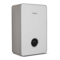
Overview of the appliance's features and models.
Table comparing features of different HIU models.
Defines correct usage and consequences of improper operation.
States compliance with European Directives and standards.
Location and purpose of the appliance's type plate.
Lists all components included in the appliance package.
Technical drawings detailing physical size and pipe connection points.
Provides a labeled diagram of all internal parts for reference.
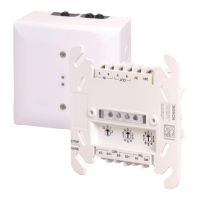
Visual representation of the appliance's electrical wiring.
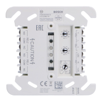
Details connections for internal components on the control unit.
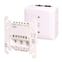
Specifies connections for external devices and power supply.
Provides a labeled diagram of all internal parts for reference.
Detailed list of all components identified in the diagrams.
Comprehensive specifications for HIU models, including dimensions and performance.
Explains how the appliance operates and its system interactions.
Rules for installation and maintenance.
Applicable country-specific rules.
Reasons for regular inspection and maintenance.
General pre-installation notices.
Requirements for water system and pipe-work.
Guidelines for water quality, pressure, and supply.
Proper routing and safety for pressure relief valve discharge pipes.
Steps for cleaning the central heating system before installation.
General requirements for appliance placement.
Specific electrical safety rules for rooms with baths or showers.
Rules for placing the appliance and required surrounding space.
Minimum clearances required when fitting the HIU into a compartment.
Illustrative diagrams for radiator heating systems.
Provides an example layout for central heating with under-floor systems.
Information and diagrams related to the appliance's mounting frame.
Step-by-step guide for fitting the support bracket and mounting frame.
Instructions on how to use the template for accurate wall mounting.
Securing the bracket and frame to the wall.
Illustrative examples of pipe-work connections to the appliance.
Guide on how to install the integral filling link assembly.
Instructions for fitting an external filling link if required.
Guide on installing the flushing valve accessory.
Information on installing a flow regulating valve if needed.
How to make hydraulic connections on the frame.
Step-by-step instructions for safely hanging the main appliance unit.
Essential rules and precautions for electrical work.
Best practices for routing power and signal cables safely.
Details on connecting external controls and thermostats.
Steps to access and work with the appliance's electrical connections.
Instructions for securing electrical cables using retainer clamps.
How the appliance protects itself and the system from freezing.
Details the by-pass feature for maintaining heat.
Explains the function for limiting return temperature for efficiency.
Procedure for cleaning the primary heating circuit.
Instructions for using the flushing kit accessory.
Step-by-step guide for filling and venting the appliance.
How to install the integral keyless filling link.
Guide for installing an external filling link.
Explains the status indicated by the LEDs on the control unit.
How to set the DHW temperature using the rotary switch.
How to set the central heating temperature using the rotary switch.
Interpreting the colored indicators on control valves.
How to activate or deactivate the pump settings lock.
Methods to check pump operational status and curve settings.
Diagram showing hydraulic head for different pump settings.
Modulating speed characteristics and performance curves for the pump.
Steps for adjusting the pump's operating curve for efficiency.
Guide to operating and navigating the Sense II controller's service menu.
Configuration parameters for the HIU, including temperature set points.
How to configure the electronic by-pass for keep-hot functionality.
Specific settings for the electronic by-pass function.
Instructions for enabling and configuring the floor drying function.
Technical data and features of the integral heat meter.
Explanation of the heat meter's display interface and navigation.
Details on connecting external signals to the heat meter.
Guide for connecting the heat meter via M-Bus.
Typical water quality parameters and requirements for district heating systems.
Typical water quality parameters and requirements for district heating systems.
Water quality parameters for DHW systems.
Graphical representation of DHW output and flow rate performance.
Explanation of the elements within the DHW performance chart.
A practical example demonstrating how to use the DHW performance chart.
Performance data graphical representation for specific CH outputs.
Explanation of the elements within the central heating performance chart.
A practical example demonstrating how to use the CH performance chart.
Performance data graphical representation for specific CH outputs.
Guidelines for testing system functionality and heat outputs.
A comprehensive checklist to ensure all commissioning steps are completed.
Instructions for securing the appliance's outer cover.
Procedures for customer handover, including documentation.
Details regarding the appliance guarantee terms and registration.
Steps for removing and cleaning the district filter element.
Instructions on how to safely drain the appliance for maintenance.
Specific steps for removing and cleaning the filter.
Templates for documenting inspection findings and measurements.
Essential step to drain the appliance before replacing parts.
Procedure for removing and replacing the plate heat exchanger.
Steps for replacing the control valves.
Procedure for replacing the differential pressure control valve.
Steps for removing and replacing the circulating pump.
Procedure for replacing the heat meter component.
Steps for replacing the expansion vessel.
Procedures for replacing DHW sensors and safety valves.
Procedure for replacing the flow turbine, regulator, and filter.
Steps for replacing the summer by-pass valve.
Procedures for replacing district and central heating NTC sensors.
Detailed steps for replacing the main control unit.
Troubleshooting guide for scenarios with no heat output from the CH system.
Troubleshooting guide for low/no flow and temperature issues.
Explains the meaning of LED indicators for fault finding.
Identifies and explains faults indicated by control valves.
Steps for calibrating control valves if they fault.
Explains fault indications for the circulating pump.
How to access and navigate the Sense II diagnosis menu.
Lists the available diagnostic menus for the Heat Interface Unit.
Details on accessing and interpreting HIU diagnostic functions.
Menu for performing function tests on the HIU.
Procedure to test the central heating pump's operation.
Resistance values for NTC sensors used in diagnostics.
| Brand | Bosch |
|---|---|
| Model | Worcester Greenstar HIU E |
| Category | Recording Equipment |
| Language | English |