Do you have a question about the Bosch DX4010V2 and is the answer not in the manual?
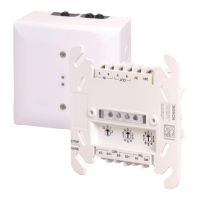
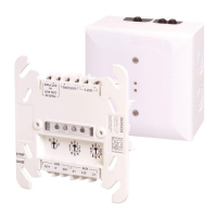
Provides an overview of the DX4010V2 as a serial interface module for control panels.
Details operating voltage, current draw, communication configuration, temperature, humidity, and control panel compatibility.
Outlines general standards and guidelines relevant to the installation process.
Diagram and description for connecting the DX4010V2 to the control panel data and auxiliary power.
Illustrates how to connect an external 12 VDC power supply to the DX4010V2.
Shows serial device-to-DX4010V2 connections using the DB9 DTE RS-232 connector.
Instructions on using jumper pins P2 to enable diagnostic LEDs for troubleshooting.
Details on using jumper pins P1 to clear ground fault conditions with connected devices.
Information on using address DIP switches to assign an address to the DX4010V2.
Explains how to create a local direct connection for remote programming.
Table listing DIP switch settings for assigning module addresses on the option bus.
Table detailing DIP switch settings for assigning module addresses on the SDI bus.
Description of the DB9 DTE RS-232 connector wiring for DTE devices like PCs.
Details on using the RJ-16 connector for remote programming with specific control panels.
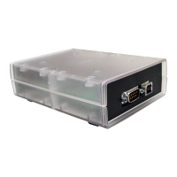
Information on connecting the DX4010V2 via USB and installing necessary drivers.
Step-by-step guide to installing the Silicon Labs CP210x USB drivers.
Steps to configure COM port settings in Device Manager and establish panel communication.
| Brand | Bosch |
|---|---|
| Model | DX4010V2 |
| Category | Recording Equipment |
| Language | English |