DX4010V2 | Installation Instructions | 6.0 Remote Programming Direct Connection
Bosch Security Systems, Inc. | 9/08 | F01U083036-01 7
5.3 Address DIP Switches
The address DIP switches are used to assign an
address to the DX4010V2.
Refer to Table 3 on page 8 for DIP switch option bus
address settings.
Refer to Table 4 on page 9 for DIP switch SDI bus
address settings.
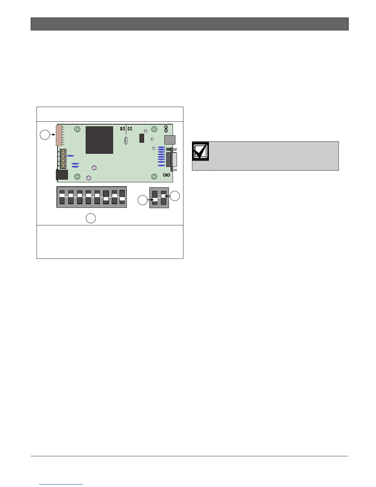
Refer to Figure 7 for proper DIP switch orientation.
Figure 7: DIP Switch Location and Orientation
ON
123456
12481632
78
64 128
2
3
4
SER
RxTx
BUS
Rx Tx
LED
P2
P3
1
DB9 GND
ENABLE
P1
1- Address DIP switches
2- Address example (option bus Address 0)
3- OFF position
4- ON position
6.0 Remote Programming
Direct Connection
The DX4010V2 can be used to create a local direct
connection for remote programming of a compatible
control panel.
Option Bus: Set the address DIP switches to
Address 0. Refer to Table 3 on page 8.
SDI Bus: Set the address DIP switches to Address
88. Refer to Table 4 on page 9.
Consult your control panel’s installation guide for
specific wiring connections.
A DB9 to DB9 null-modem cable is
required when using the direct
connection method.