INSTALLATION
Step 1
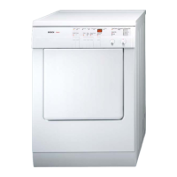
Unpack the Dryer
Carefully remove the packing material from the
outside of the dryer.
Step 2
Inspect the Dryer
Thoroughly inspect the dryer, prior to installation, for
possible freight or cosmetic=damage. Report any
damage immediately. Cosmetic damage must be
reported within 5 days of installation.
Be sure to install the exhaust according to all
governing codes and ordinances. Rigid metal duct is
recommended for venting this dryer. If flexible metal
duct is used, be sure it is fully supported when the
dryer is in its final position. Excess ducting should be
trimmed off to avoid sagging or kinking of the
ductwork.
Step 3
Position Dryer near Installation Area
Move the dryer so that it is within four feet of the
desired position.
Note: Corrugated packing materia, may be used to
protect the floor. Do not use corrugated
material with staples.
Step 4
Exhaust Duct
(Model W-FA 3500 Only!)
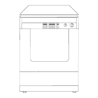
The WTA 3500 must be exhausted to the outdoors.
The duct may be connected to the left, right or back
of the WTA 3500, electric vented dryer. If connecting
to the left or right hand side of the dryer, remove the
sealing cover from the side to be used, as shown in
Figure 4.
1. To reduce the risk of fire, this dryer
MUST BE EXHAUSTED OUTDOORS,
when installed in an alcove or closet.
2. DO NOT use non-metal duct with this
dryer.
3. DO NOT use duct smaller than 4
inches in diameter.
4. DO NOT use exhau=t hoods with
magnetic latches.
5. DO NOT exhaust the dryer into a
chimney, furnace cold air duct, attic,
crawl space, or any other ductwork
used for venting.
6. DO NOT install flexible duct in an
enclosed wall, ceiling or floor.
7. DO NOT crush or kink the duct.
8. Do clean and inspect the exhaust
system on a regular basis; once a
year, at a minimum.
9. The exhaust duct must end with
swing out damper(s).
Figure 4.
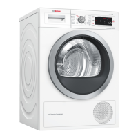
The sealing cover should then be placed over the
open vent opening at the back of the dryer, as shown
in Figure 5.
6
Figure 5.
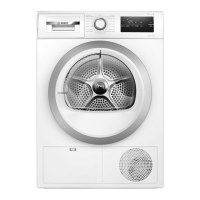
The connecting piece supplied with your WTA 3500
dryer must then be inserted in the vent opening that
will be used. See Figure 6.
 Loading...