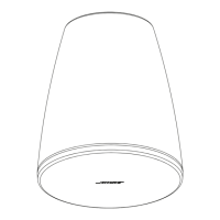
English • 5Installation Guide • DesignMax DM5SE
BoseProfessional.com
Setup
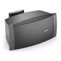
70V/100V
8Ω
Note: The loudspeaker is not
rated for use with a rigid conduit.
The loudspeaker is suitable
for a flexible conduit or wiring
connection only.
8Ω
8Ω
8Ω
8Ω
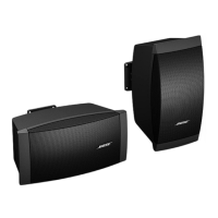
Loudspeaker Settings
70V
3W 6W 12W 25W 50W*
8Ω
6W 12W 25W 50W NC**
100V
** NC: No Connection (do not use)* Factory default
Transformer Tap Setting
Set tap by turning. Use a flat head screwdriver.
Wiring the Loudspeaker
Wire Gauge
The DesignMax DM5SE loudspeaker is designed to work with 18 AWG (0.8 mm
2
) to 14 AWG (2.1 mm
2
) size wire only.
Connection Diagrams
Expose six millimeters (¼ inch) of bare wire to attach to the terminals.
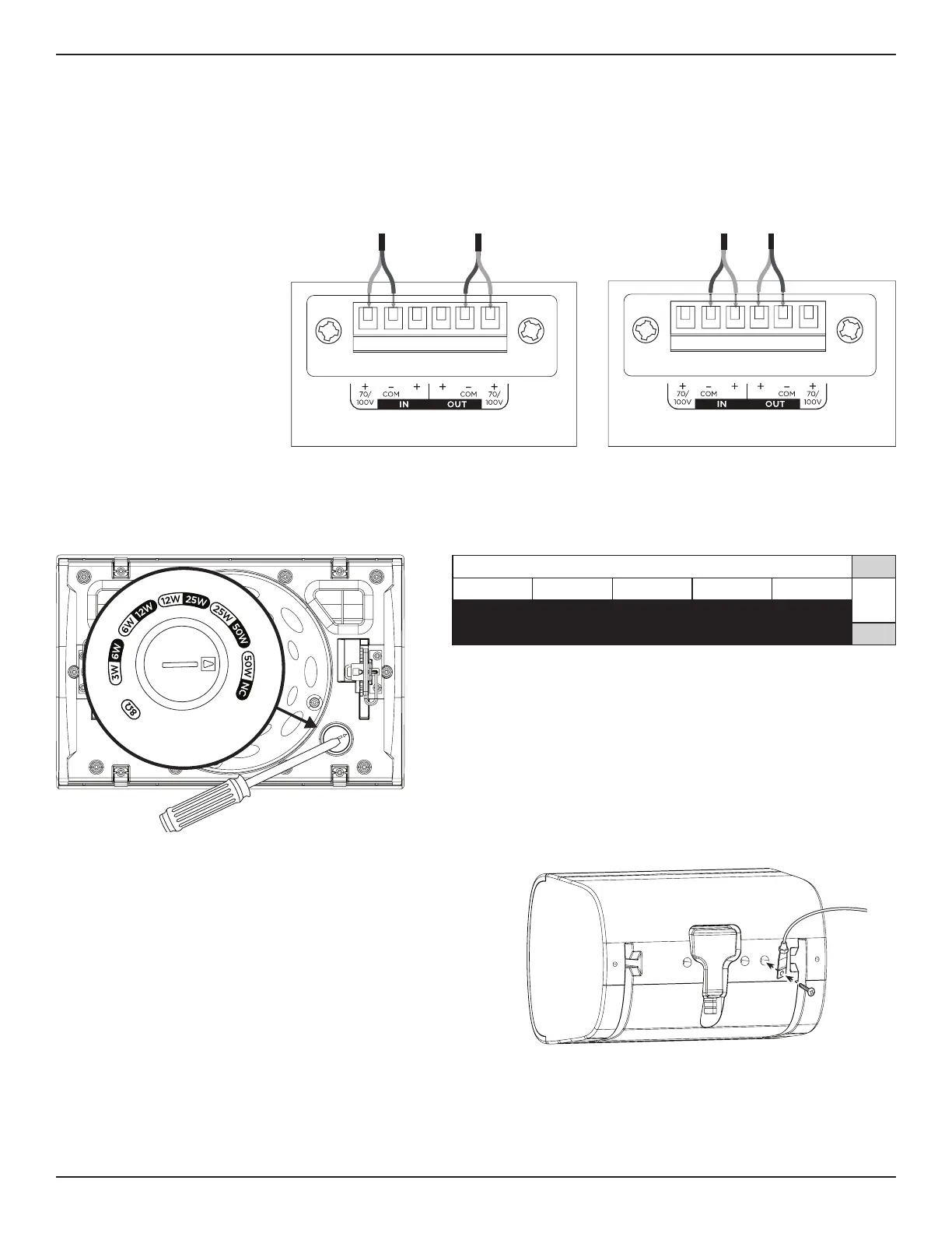
Using a Safety Cable
Some regional construction codes require the use of a secondary
method of securing loudspeakers to support structures
to provide additional safety. Choose a mounting position,
method, and hardware consistent with local building codes and
regulations.
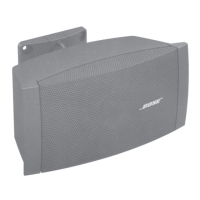
A safety cable can be attached to the loudspeaker using the
threaded insert on the back of the enclosure.
The insert is sized for an M6 screw (not included) with a depth of
15 millimeters (0.59 inches).
 Loading...