27
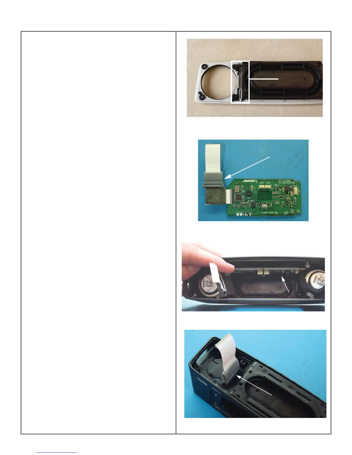
Boost PCB
Slot
Figure 24. Boost PCB Slot
3. Boost Board Installation
3.1 When installing the Boost PCB, ensure the
board is placed in the PCB slot as you push
down on the board to connect it to the main
board. Figure 24.
4. Main and Boost PCB Placement
Note: A new FFC grommet should be used to
avoid potential air leaks.
Note: If the baffl e was removed, a new baffl e
should be used to avoid air leaks caused by
deformation of the baffl e wiper gasket. The
baffl e must be inserted straight down to prevent
the gasket from rolling under and causing an air
leak.
4.1 Insert the grommet over the FFC as shown.
Figure 25. FFC Grommet
4.2 Lower the Main PCB into the cabinet at an
angle so the switches do not scrape against the
cabinet. Then feed the boost board through the
top of the assembly and make the connection
between the boost board and the main board.
Feed the FFC with grommet through the slot
in the rear baffl e. Ensure both sides of the
grommet nub is fully seated in the slot. Figure 25
and 27.
4.3 The back edge of the Main PCB should rest
on the shelf of the rear baffl e. Figure 26.
4.4 Once fully inserted, rotate the front edge
of the Main PCB upward until the switches are
aligned to the holes in the cabinet.
4.5 With the speaker harness lined up with the
notch in the Boost PCB, rotate the Boost PCB
into position. Line up its connector with the
connector on the AMP PCB.
Note: Ensure the speaker harness is dressed
as described in the Speaker Harness Dressing
instructions procedure 2.
Grommet Location
Baffle Shelf
Grommit Nub
Figure 25. FCC Grommet
Figure 27. Grommet Seated in Baffl e Slot
Figure 26. Main PCB Placement
ASSEMBLY KEY POINTS
 Loading...