26
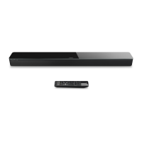
Speaker Terminals
Figure 22. Driver Placement
When assembling the unit, reverse the disassembly
procedures. The following assembly instructions
provide key points that are important to consider
when assembling the unit.
Note: To avoid stripping screws, fi rst rotate the
screw counter clockwise to locate the thread holes
and then clockwise to tighten.
1. Driver Installation
1.1 When installing the drivers, make sure to
place the speaker terminals toward the bottom.
Figure 22.
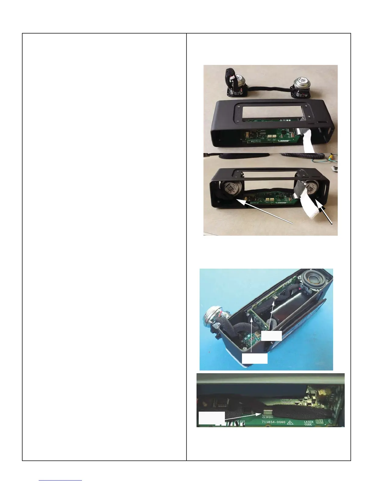
2. Speaker Harness Dressing
2.1 Run the speaker harness through the notch
in the Boost PCB. Figure 23.
2.2 The speaker harness should be dressed
taught under the clip on the Main PCB. This will
prevent the harness from contacting the moving
passive radiator when assembled. Figure 23.
Note: If the harness is too taught, the right driver
will rotate out of position.
Notch in
Boost Board
Clip on
Main PCB
Clip on
Main PCB
Figure 23. Driver Harness Dressing
ASSEMBLY KEY POINTS

 Loading...