25
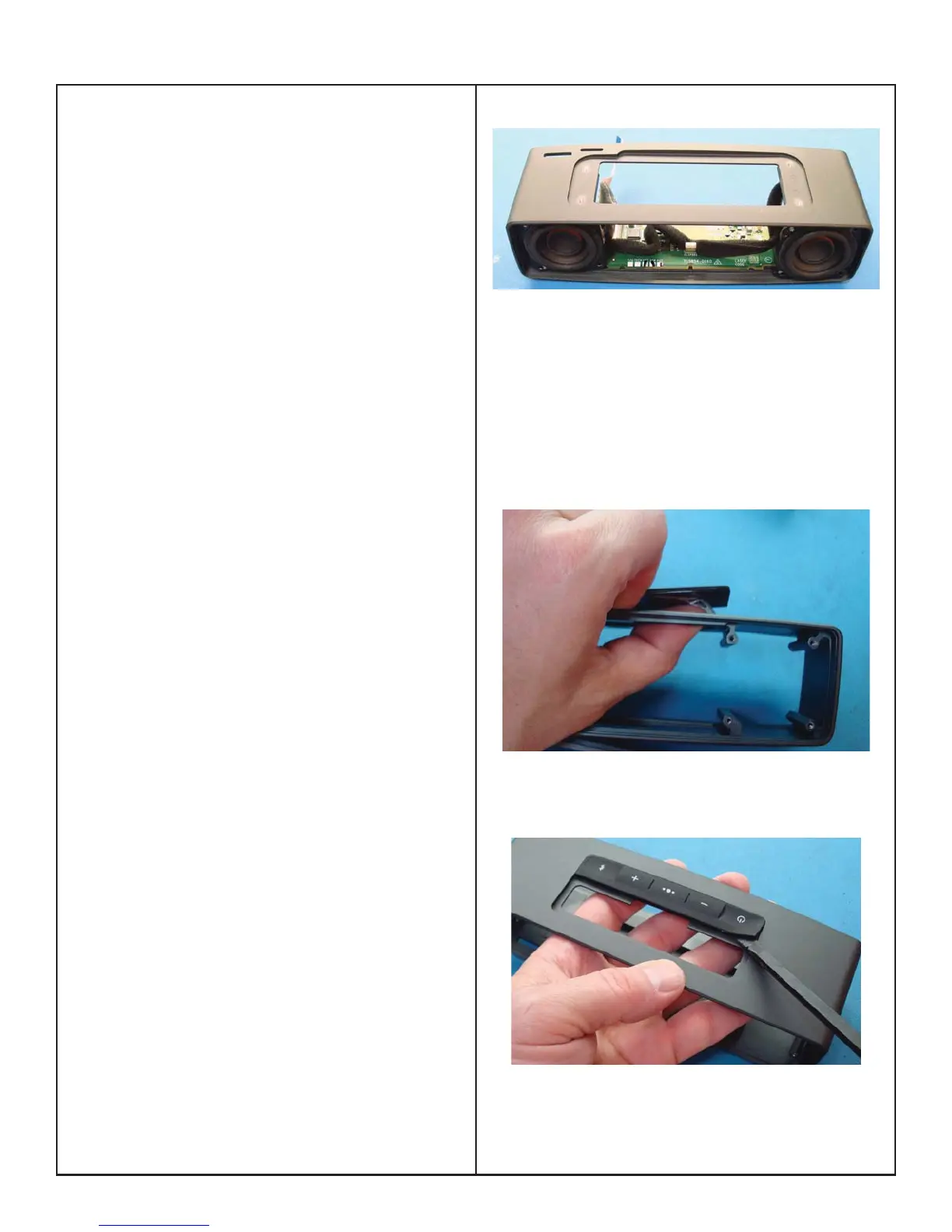
4. Main PCB Removal
Important Note! To avoid damage to the switches
on the Main PCB, the front and rear baffl e should
be removed. The Main PCB is held in place by a
shelf on the front and rear baffl es which restricts
the ability of the Main PCB to be rotated downward
enough for the switches to clear the cabinet holes.
4.1 Perform procedures 1, 2, 3.1 and 3.2 to gain
access to the Main board.
4.1 Detach the speaker wire from the wire clip on
the main board.
4.1 lift upward on the main board and remove.
5. Lens Removal
5.1 Perform procedures 1, 2, 3 and 4 to gain ac-
cess to the lens
5.2 The Lens is held in place by Pressure Sensitive
Adhesive (PSA). Insert your thumbs into the cabinet
and press upward on the Lens to release the PSA.
Figure 20.
6. Button Pad Removal
5.1 Perform procedures 1, 2, 3 and 4 to gain ac-
cess to the button pad.
6.1 Insert a plastic tool, such as a spudger, under
the corner of the button pad and lift it up. Figure 21.
6.2 Peel up the button pad.
Figure 19.
Figure 20.
Figure 21.
DISASSEMBLY PROCEDURE
 Loading...