• DYNAGLIDE™ Feature Light: The DYNAGLIDE Feature light is
located adjacent to the STALL light, and is visible only when illuminated
indicating that the Dynaglide Feature is activated. The Dynaglide Feature
provides a controlled low speed rotation (approximately 50,000-90,000
RPM) of the Rotablator™ Burr for use during intraprocedure exchange of
Rotablator Rotational Angioplasty System advancer or catheter. The
Dynaglide Foot Pedal button is used to turn the Dynaglide Feature on or off.
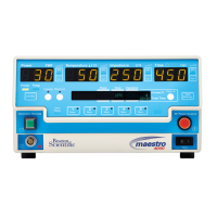
• Event Timer: Located below the tachometer, the event timer records how
long the foot pedal has been continuously depressed with the air turbine and
burr spinning. When the foot pedal is released, the timer continues to
display the previous event time. Depressing the foot pedal resets and restarts
the timer. For additional information on operating range, accuracy and
precision, see Table 1.
• Procedure Timer: The procedure time is the sum of the individual event
times and indicates the total time the burr has been spinning during the
procedure. For additional information on operating range, accuracy and
precision, see Table 1.
Table 1
• Reset Button: Pushing the reset button resets the event and procedure
timers to zero.
• Turbine Connector: The gas line connector on the right-hand side receives
the advancer gas hose and supplies filtered, regulated compressed gas to the
advancer when the foot pedal is depressed.
• Dynaglide Foot Pedal Connector: The gas line connector on the left-hand
side receives the Dynaglide Foot Pedal pink hose, and is used to activate or
deactivate the Dynaglide Feature mode of operation.
• Fiber Optic Tachometer Cable Connector: These two female connectors
receive the mating male connectors from the fiber optic tachometer cable.
The orientation of the cable to the female connector is not important. The
fiber optic tachometer cable carries light pulses which the console uses to
determine the rotational speed of the gas turbine and burr.
Rear Panel
• Line Cord: This cable plugs into a conventional 100-120 V a.c. or
220-240 V a.c. receptacle (as indicated on the name plate located on the
rear of the console) and provides power to the console. In Germany, line
cord connections must be to a VDE 0107 compliant installation. The ground
wire of the line cord is internally connected to the console chassis.
• Fuses: The fuses protect the console’s electrical components in the event of
a serious electrical fault. If a fuse should fail, refer to Appendix B for
replacement instructions.
• Potential Equalization Connector: Located to the left of the fuse, the
potential equalization connector is provided to allow potential equalization
between various hospital electrical instruments. In Germany, the potential
equalization connections must be made to a VDE 0107 compliant installation.
•
Compressed Gas Inlet: This male connector, located in the top center of the
rear panel, mates to the corresponding connector on the supply line from the
compressed gas source. Pressure at this inlet should always be between 620.5
and 758.4 kPa (90 and 110 psi) with a minimum flow capacity of 140 l/min
(5 standard cubic feet per minute (scfm)). Pressure will be reduced by the
console to operating limits. An internal pressure-relief valve protects against
input pressures in excess of 792.9 kPa (115 psi) and creates a loud hissing
noise in the console when the pressure exceeds 792.9 kPa (115 psi).
• Dynaglide Foot Pedal Connectors: These two connectors receive the mating
pair of connectors from the Dynaglide Foot Pedal. The green hose connects to
the right-hand connector and the blue hose to the left-hand connector.
Other
• Dynaglide Foot Pedal: The foot pedal is used as an on/off control for the
advancer gas turbine. The foot pedal is also fitted with a valve which vents
any compressed gas in the foot pedal hose when the pedal is released,
permitting the burr to stop rapidly. The foot pedal is mounted in a protective
shroud which inhibits accidental actuation.
• The Dynaglide Foot Pedal button located on the right side of the foot pedal
housing is used as an on/off control for the Dynaglide Feature mode of
operation. When the Dynaglide Feature is on, the green DYNAGLIDE
Feature light is illuminated on the console front panel.
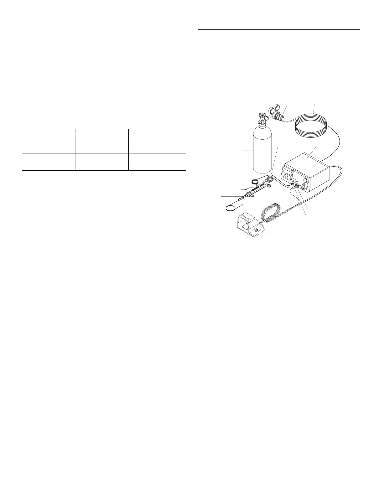
Assembly and Setup of the Rotablator Console
The recommended control console system, illustrated in Figure 2, consists of an air
or nitrogen pressure regulator mounted on a compressed gas cylinder, connected to
the Rotablator Console via a supply hose (provided with the console). The gas
cylinder is shown for illustration only, and is not of the recommended size. Gas
cylinders must be properly secured per standard procedures.
Note: It may also be possible to operate this system from a hospital (house) gas
system, as discussed in Appendix C. The Rotablator Console is not suitable for
use with in-hospital (house) compressed gas lines in Germany due to pressure
and flow incompatibilities, unless connections are made in accordance with
DIN 13 260.
Figure 2
Control Console System
To put the Rotablator Console into service, proceed as follows:
WARNING NEVER use oxygen as the propellant for the Rotablator
Rotational Angioplasty System. NEVER connect the
regulator to an oxygen cylinder. Oxygen combined with oil or
other combustibles in the system can result in an explosion.
WARNING This device is not to be used in the presence of
flammable anesthetics.
1. Procure a compressed gas cylinder containing either compressed air or nitrogen.
In Germany, only compressed air may be used, gas cylinder fittings must be
according to DIN 477 Teil 1 (Druckluft), and compressed gas cylinders must
be approved by the German government (Bauartzugelassen). A cylinder
capacity of at least 2250 l (79.46 standard cubic feet) is recommended, and
will provide approximately 20 minutes of service with the Rotablator
Rotational Angioplasty System advancer running at full speed. Larger
cylinders may be used. A fully charged spare cylinder should always be
available.
2. Secure the compressed gas cylinder in accordance with hospital procedures.
3. Obtain a cylinder regulator (relieving type is preferred) capable of
delivering at least 140 l/min (5 scfm) at 620.5-758.4 kPa (90-110 psi).
Make certain that the cylinder regulator fitting is compatible with the gas
cylinder being used. In Germany, only compressed air may be used, gas
cylinder fittings must be according to DIN 477 Teil 1 (Druckluft), and
compressed gas cylinders must be approved by the German government
(Bauartzugelassen).
4. Connect the supply hose gas coupling (provided with the Rotablator
Console) to the outlet port of the cylinder regulator.
Unless local government regulations require otherwise, the gas coupling
is configured with .6 cm (¼”) MNPT threads. Verify the type of gas
coupling provided with the Rotablator Console prior to procuring a
cylinder regulator.
If necessary, use suitable adapters to make the connection. In some
countries, the regulator end of the gas supply hose has a permanently
attached warning tag to remind users not to connect it to oxygen sources.
Do NOT remove this tag.
4
Display Operating Range Accuracy Precision
Turbine Pressure Gauge 0-689.5 kPa or 0-100 psi ± 5% 6.9 kPa or 1 psi
Rotational Speed Display 0-250,000 RPM ± 1.5% 1,000 RPM
Event Timer 00:00-59:59 ± 0.1% 1 second
Procedure Timer 00:00-59:59 ± 0.1% 1 second
 Loading...