5
5. Remove the cylinder cap and attach the regulator, tightening the
cylinder fitting firmly.
The regulator should be adjusted so that the outlet pressure is in the range
620.5-758.4 kPa (90-110 psi).
6. Connect the supply hose to the inlet connector on the back of the console.
In most countries, the inlet connector is marked AIR OR NITROGEN. In
Germany, the inlet connector is marked ‘Druckluft’. Verify that the
compressed gas being placed into service is in accordance with the inlet
connector marking.
7. Connect the foot pedal to the console by first locating the three
connectors at the end of the foot pedal triple hose.
Insert the green hose connector in the right-hand and the blue hose
connector in the left-hand mating receptacles on the rear of the Rotablator™
Console. These receptacles are labeled FOOT PEDAL or marked with a foot
pedal symbol. Connect the pink hose connector to the left-hand connector
on the front panel.
8. Connect the power cord to a properly rated hospital grade receptacle
(as indicated on the nameplate located on the rear of the console).
In Germany, power connections must be made to a VDE 0107 compliant
installation, and the potential equalization stud must be connected.
9. Open the compressed gas cylinder valve, or line valve if running on
house air (see Appendix C), to supply compressed gas to the console.
Note that the cylinder regulator gauge indicates the pressure of the gas
remaining in the cylinder. The regulator should be adjusted so that it never
supplies more than 758.4 kPa (110 psi) to the console, and no less than
620.5 kPa (90 psi). Do not initiate the procedure if less than 3,447 kPa
(500 psi) of gas remains in the tank.
WARNING If a hissing noise is detected from the console, check to make
sure that the gas pressure supplied to the air or nitrogen
connector does not exceed 758.4 kPa (110 psi). The console
is equipped with a pressure relief valve to protect against
excessive inlet pressure. Do NOT operate the Rotablator
Console with gas pressures in excess of 758.4 kPa (110 psi),
as a compressed gas hose may burst.
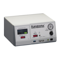
10.Push the console power switch and confirm that the green light
illuminates indicating power is on.
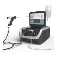
The Rotablator Console is now ready for use. Console placement,
ventilation, splash protection and cleaning instructions may be found below
in the section entitled: “Operation, Cleaning and Disposal Instructions.”
Operation, Cleaning and Disposal Instructions
1. Ventilation
The Rotablator Console uses natural convection cooling to maintain the
proper operating temperature for internal components. Cooling vents are
located on the bottom and rear of the console enclosure. In order to ensure
proper ventilation of the console, it must be placed on a hard, flat surface
with a minimum of 2.5 cm (1”) clearance maintained around all sides and
bottom of the enclosure. Do not set on drapes or bedding.
2. Splash
The Rotablator Console is designed to be placed outside of the sterile field.
Care should be taken to protect the console from splash and ingress of
liquids which may cause damage to internal components.
3. Cleaning
The Rotablator Console and Dynaglide™ Foot Pedal should be cleaned
regularly by wiping with a soft cloth dampened with a mixture of water
and mild detergent. Never immerse in fluids. The use of solvents or
abrasive cleaners may cause damage to the plastic parts of the console and
should be avoided.
4. Disposal
The user should follow local and national regulations for disposal of
electronics when disposing of this unit. The console contains no batteries or
heavy metals.
References
For coronary use, please refer to the Rotablator Rotational Angioplasty System
physician training program course materials for a listing of publications, or
contact your local sales representative. Additional articles, including
publications on the use of the Rotablator Rotational Angioplasty System in the
peripheral vasculature are available upon request. Please contact your local
sales representative to obtain a listing.
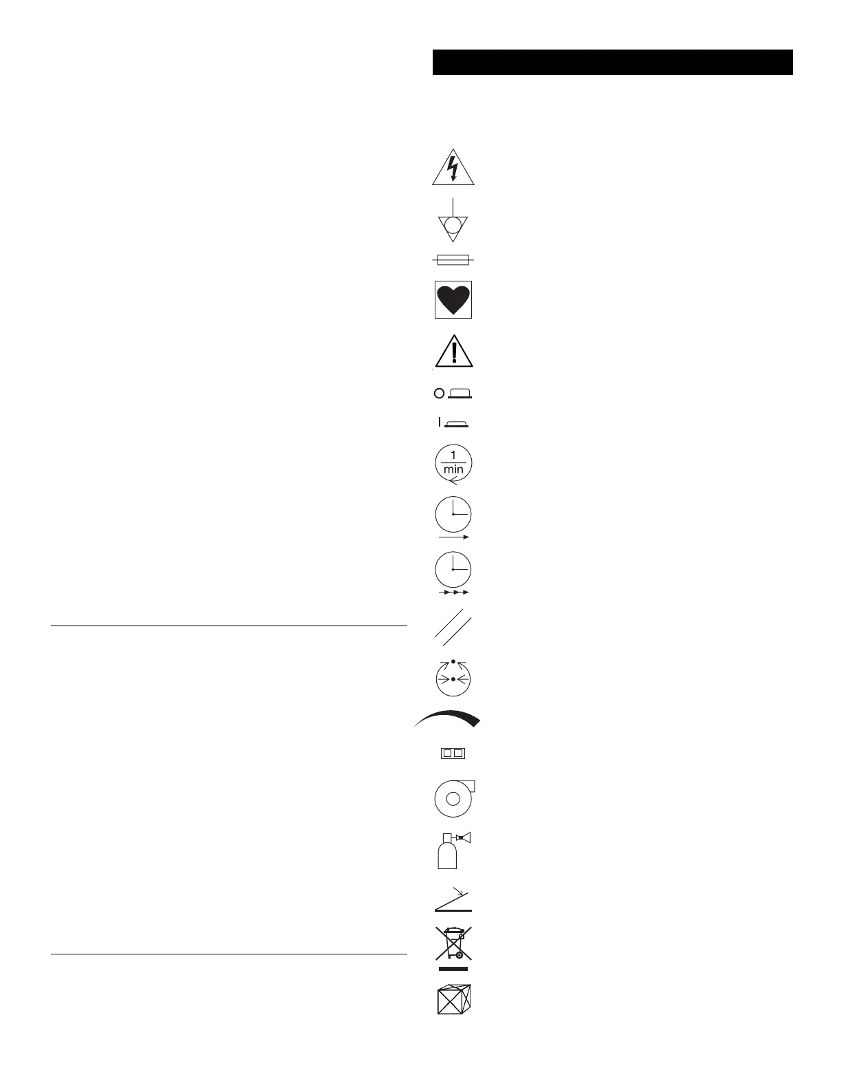
The symbols shown below may be present when required by specific safety
testing agencies such as Underwriters Laboratories (UL), Canadian Standards
Association (CSA), etc.
Dangerous voltage. To reduce risk of electric shock, do NOT
remove cover. Refer servicing to qualified service personnel.
Potential equalization connector. Provides means of achieving potential
equalization between hospital instruments. In Germany, connection
must be to a VDE 0107 compliant installation.
Indicates that a fire hazard may exist if fuses are not replaced as
marked.
Indicates type CF equipment.
Attention! Consult Accompanying Documents.
Console power is OFF when the power switch is in
the OUT position.
Console power is ON when the power switch is in the IN position.
Rotational Speed. Displays speed of the burr in RPM.
Event Time. Displays the length of time the foot pedal
has been continuously depressed.
Procedure Time. Displays the sum of the individual event times.
Reset. Resets the event and procedure timers to zero.
Turbine Pressure. Displays the pressure of the compressed
gas being supplied to the advancer gas turbine.
Turbine pressure increases with clockwise rotation.
Fiber optic connector.
Turbine. Connector for the advancer gas hose.
Compressed Gas Inlet. Connector for the supply line
from the compressed gas source.
Foot pedal connectors.
Proper disposal of electronic equipment is required according to
EN directive 2002/96/EC, Waste of Electrical and Electronic
Equipment (WEEE).
Contents of Package.
Appendix A - Symbol Translation Key
 Loading...