2
7
Take Care
3. Operation
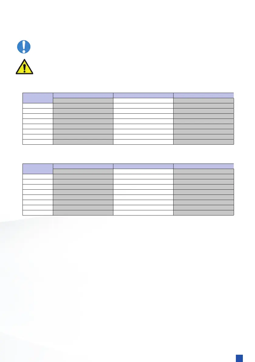
3.1 Maximum water flow rates
The following tables give maximum ow rates through the tube stack for either
single, two or three pass conguration, using either sea or fresh water.
Max Recommended Flowrate (I/min) Max Recommended Flowrate (I/min) Max Recommended Flowrate (I/min)
EC range 50 80 170
FC range 80 120 230
FG range 110 170 320
GL range 200 290 560
GK range 300 450 900
JK range 400 600 1200
PK range 650 1000 2000
RK range 900 1400 2800
Max Recommended Flowrate (I/min) Max Recommended Flowrate (I/min) Max Recommended Flowrate (I/min)
EC range 75 120 255
FC range 135 200 380
FG range 180 270 530
GL range 320 470 900
GK range 460 690 1400
JK range 660 1000 2000
PK range 1000 1500 3000
RK range 1400 2150 4300
Sea Water Application (Maximum 2 m/s)
Fresh water Application (Maximum 3 m/s)
3-Pass
Type
3-Pass
Type
3.2 General information
The oil cooler should be pressurized on the oil (shell) side such that it is at a higher pressure than
the water (tube) side. This will ensure that if a leak occurs it will be detected by a reduction in the
oil level and the oil will not be contaminated. A dierential pressure of 2 bar would be sucient. It
is essential that the following instructions are followed to prevent corrosion/erosion of the heat
exchanger:
a) Always maintain the water pH to within correct levels. The ideal water pH should be kept
within 7.4 to 7.6. On no account should it be below 7.2 or above 7.8.
b) Minimum water velocity of 1m/s should be used.
c) Ensure compliance with water quality and maximum permissible pressure requirements.
d) Air must be adequately vented from both circuits.
e) Stagnant water should not be allowed to accumulate in the oil cooler. If it is not in use
for any period of time the water should be drained o.
2-Pass 1-Pass
2-Pass 1-Pass