3
4
5
6
8
8A
11
12
23
14
13
16
24
3
4
5
6
8
11
12
23
14
13
16
24
3
4
5
6
8
11
12
23
14
13
16
24
1
2
3
4
5
6
7
8
1
2
G
HF
EB
SW1
SW2
SW3
SW4
SW5
ON
OFF
A
B
D
C
5
6
21
8
8A
22
11
12
23
14
13
16
3
4
7
5
6
8
9
SW
B
3
4
5
6
8
8A
11
12
23
14
13
16
24
VA/200
VSI/200
43,5
45
7,5
57
210
106
A
B
64,5
210
145
GB
INSTALLATION
INSTRUCTIONS
VSI/200 ENTRANCE SELECTOR
This unit permits the selection of
two entry panels and is configured
to create the following systems:
• Single or multi-family systems
with several entrances using the
same number of selectors as there
are entry panels minus one.
• Residential systems using the
unit as a block selector.
Operating characteristics
• Sequential selection of entry
panel or supplementary camera by
the monitor.
• Protection of any connections
installed and management of the
engaged signal irrespective of
whether the unit is used as a selec-
tor for several entry panels or as a
block selector in residential
systems (the protection may be
disabled by connecting jumper
SW2, figure 1).
• The selector is equipped with an
amplifier which regenerates the
call signal.
• Possibility of connecting up to
a
ni
-
i
-
la
le
o
A
:
à
l-
-
N
o
a
N
il
o
three internal units to the same call.
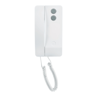
• Possibility of trading the origin of
an external call by means of diffe-
rent tones which correspond to two
different entry panels.
To obtain this function: connect ter-
minal 8A of VSI/200 selector to ter-
minal 8A of VA/200 power supplier
(terminal board B) and remove the
jumper SW from VA/200 power
supplier as shown in figure 2.
WARNING. A differentiated landing
call tone is not available in this con-
figuration.
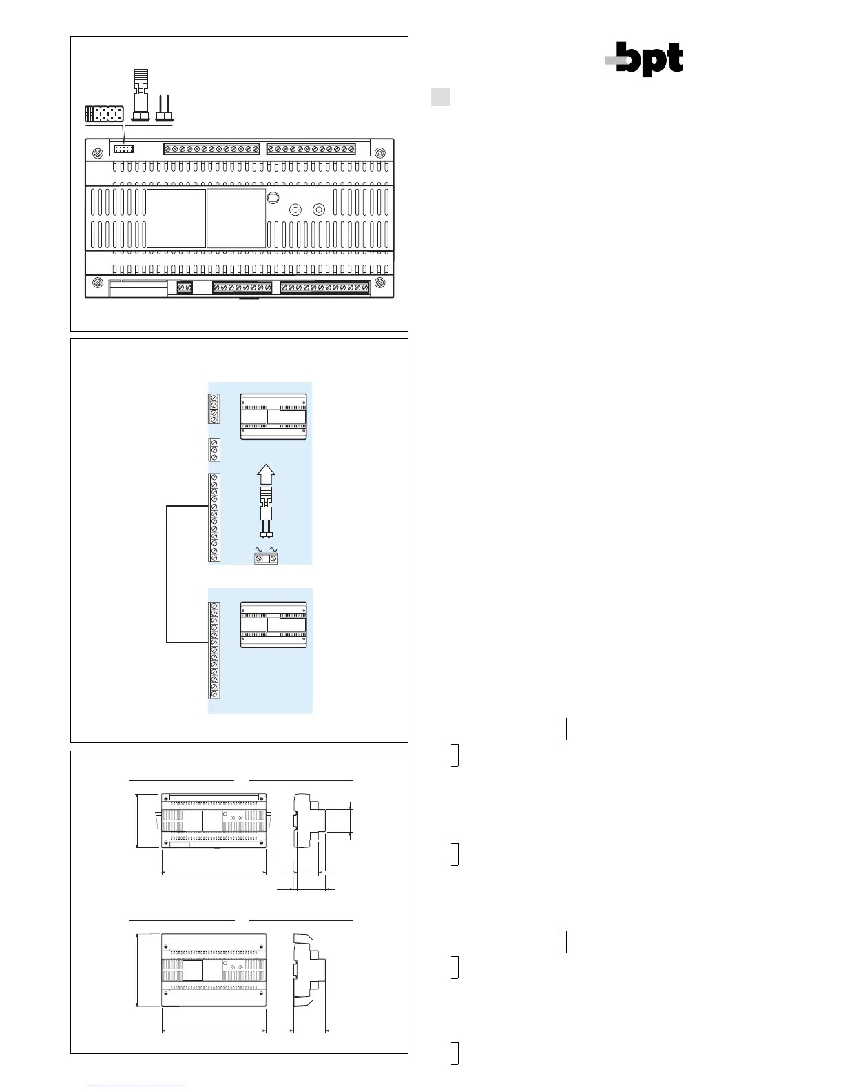
Function of each terminal, figure 1
Terminal block B (to power supplier
or preceding selector
3 video signal
(
1
)
4 video signal shield
5 17,5 supply voltage
6 + to entry panel
8 call 1 common
8A call 2 common
11 audio signal to monitor
12 audio signal to entry panel
23 auxiliary door release button
14 entry panel activation
13 + 12V supply voltage to
16 door release solenoid
24 engaged signal input
Terminal block E (to entry panel no. 1)
Terminal block F (to entry panel no.
2 or subsequent selector)
3 video signal
(
1
)
4 video signal shield
5 17,5V supply voltage
6 + to entry panel
8 call common
11 audio signal to monitor
12 audio signal to entry panel
23 auxiliary door release button
14 entry panel activation
13 + 12V supply voltage to
16 door release solenoid
24
(
1
) coaxial cable connection; twisted
pair connection to terminal blocks
B-E-F:
3 positive video signal
4 negative video signal
Terminal block G (services)
1 call 1 input
2 call 2 input
3 12V DC power input
4 engaged signal output (fo
residential systems)
5 general reset
6 changeover enable-next selec
tor
7 changeover enable-previou
selector
8 entry panel selection
Terminal block H (services)
1 call 1 output
2 call 2 output
SW jumper functions, in ON posi-
tion, figure 1
1 repositioning of selectors fol
panels activatedby the monito
(only the jumper of the last
selector must be set in position
ON while all preceding selec-
tors must be set to OFF).
2 deactivation of call protection
3 resetting of engaged entry
panels on audio entry systems
by replacing the handset.
4-5 activation of general reset (on
residential systems.
NOTE. The selector is supplied
with SW1 jumper wired in (installa-
tion with 2 entry panels).
Technical features
• Supply voltage: 14,5÷17,5VDC
or 12VDC.
• Current demand: max. 80mA
(7mA quiescent).
• Working temperature range
from 0 °C to +35 °C.
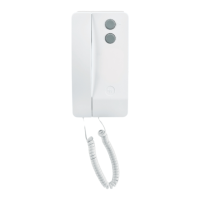
• Dimensions: 12 DIN units, low
profile module, figure 3.
The unit can be installed withou
terminal covers, in boxes fitted
with DIN guide (EN 50022).
See figure 3A for overall dimen
sions.
Alternatively, it can be wall
mounted using the DIN guide
provided, and applying the ter
minal cover.
See figure 3B for overall dimen
VSI/200
BPT S.p.A.
30020 Cinto Caomaggiore
Venezia - Italy