EasyManua.ls Logo

Bpt VSE/200.01 User Manual

Bpt VSE/200.01
32 pages
To Next Page IconTo Next Page
Page #1 background imageLoading...
Page #1 background image
1
1
2
VSE/200.01
P/3-XP/3
I
ISTRUZIONI
PER L’INSTALLAZIONE
SELETTORE PER
INTERCOMUNICANTI VSE/200.01
Il selettore permette di inserire grup-
pi di derivati interni intercomunicanti
in un impianto con derivati interni
standard (sistema 200).
E’ dotato di un generatore a nota
continua per la chiamata fra i deriva-
ti intercomunicanti.
L’apparecchio permette di effettuare
conversazioni tra intercomunicanti
anche durante una comunicazione
tra posto esterno ed un altro inquili-
no.
Durante una comunicazione interna o
con il posto esterno, l’accensione di
un LED rosso sui derivati (se presen-
te) segnala che la linea è occupata.
Mentre è in corso una conversazione
tra intercomunicanti, il selettore
garantisce la completa separazione
audio (e quindi la riservatezza)
rispetto al posto esterno.
L’apparecchio consente, in impianti
videocitofonici, l’utilizzo del derivato
citofonico intercomunicante, previo
inserimento, nel mod. C/200, del con-
densatore EKC/200.
In citofonia il condensatore EKC/200
deve essere utilizzato negli impianti
con segreto di conversazione e
citofoni C/200.
Con questo selettore è possibile rea-
lizzare impianti con derivati interni
attivati dalla stessa chiamata oppure
da una chiamata individuale.
Il selettore per intercomunicanti può
essere installato sia nel supporto da
parete (fig. 2), nel citofono XC/200
(fig. 3),in una normale scatola di deri-
vazione (90 x 90 x 40 mm) oppure su
guida DIN (EN 50022) (fig. 4).
Funzione dei morsetti (fig. 1)
Morsettiera IN
5 14,5 ÷ 17,5V alimentazione
6 + selettore (videocitofonia)
5 11V alimentazione
21 + selettore (citofonia)
7 chiamata n. 1 dal posto esterno
8 audio dal posto esterno
9 audio al posto esterno
7A chiamata n. 2 dal posto esterno
7B chiamata n. 3 dal posto esterno
Morsettiera OUT
8 audio al derivato interno
9 audio dal derivato interno
13 comune chiamata intercomuni-
cante
17 uscita occupato (LED rosso)
18 ingresso comando luce scale
19 ingresso comando autoinseri-
mento
Ponticello SW1 (fig. 1)
Questo ponticello è da inserire quan-
do il selettore viene utilizzato negli
impianti citofonici senza segreto di
conversazione.
Caratteristiche tecniche
Alimentazione: 14,5 ÷ 17,5Vcc.
Assorbimento: max. 200mA (20mA
a riposo).
Generatore di chiamata a nota con-
tinua per servizio di intercomunica-
zione.
Temperatura di funzionamento: da
0 °C a +35 °C.
Dimensioni: 60x44x16 mm (fig. 5).
ESPANSIONE DI CHIAMATA
A 3 PULSANTI P/3 E XP/3
Permette di trasformare un semplice
citofono C/200 (P/3) o XC/200 (XP/3)
in un apparecchio intercomunicante.
Nel citofono C/200 si possono instal-
lare un massimo di 4 P/3 e nel citofo-
no XC/200 due XP/3.
Funzione dei morsetti (fig. 6-7)
12 uscita chiamata dal posto sterno
7 ingresso chiamata dal posto
sterno
13 comune chiamata intercomuni-
cante
14 chiamata al derivato n. 1(4-7-10)
15 chiamata al derivato n. 2 (5-8-11)
16 chiamata al derivato n. 3 (6-9-12)
Istruzioni per l’uso del citofono
intercomunicante
Per chiamare uno degli apparecchi,
alzare la cornetta, premere il pulsan-
te desiderato (il segnale di chiamata
è una nota a tono continuo) e atten-
dere la comunicazione.
La conversazione interna non può
essere sentita all’esterno.
La chiamata proveniente dal posto
esterno è caratterizzata da una nota
bitonale (se l’apparecchio chiamato
è in conversazione, la chiamata è
segnalata in forma attenuata).
Se una chiamata dall’esterno arriva
durante una conversazione interna e
si desideri quindi entrare in comuni-
cazione con il visitatore, è necessario
che tutte le cornette vengano prima
riagganciate; sollevando quindi la
cornetta dell’apparecchio chiamato
si potrà conversare con il visitatore
esterno.
2
7B
7A
9
8
7
21
6
5
SW1
8
9
13
17
18
19
1
1
2
3
1
2
4
60 mm
44 mm
16 mm
5
5789
••
12
7
13
14
15
16
P/3
7
5
7
8
9
C
12
7
13
14
15
16
XP/3
8
BPT S.p.A.
30020 Cinto Caomaggiore
Venezia/Italy
12.2000/2402-8877
Question and Answer IconNeed help?

Do you have a question about the Bpt VSE/200.01 and is the answer not in the manual?

Bpt VSE/200.01 Specifications

General IconGeneral
BrandBpt
ModelVSE/200.01
CategoryIntercom System
LanguageEnglish

Summary

Installation Instructions

Selector for Intercom Units VSE/200.01

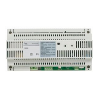
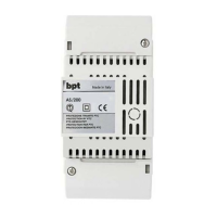
Details the VSE/200.01 selector for intercom systems and their features.

Terminal Block IN Functions

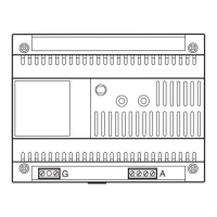
Explains the function of each terminal on the input block (fig. 1).

SW1 Jumper

Describes the purpose and use of the SW1 jumper for specific installation types.

Technical Specifications

Lists key technical data like voltage, current, dimensions, and operating temperature.

Call Expansion P/3 and XP/3

Explains how to expand intercom calls using P/3 and XP/3 buttons.

Terminal Block OUT Functions (fig. 6-7)

Details the function of each terminal on the output block.

Intercom Handset Usage Instructions

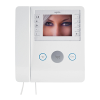
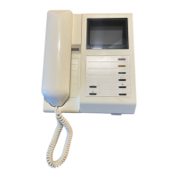
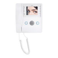
Provides guidance on operating the intercom handset, call tones, and conversation.

System Wiring Diagrams

Citofonia Sistema 200 Diagrams

Presents wiring diagrams for the Citofonia Sistema 200.

Audio Entry System 200 Diagrams

Wiring diagrams for the Audio Entry System 200.

Conductor Sections

Wire Cross-Section Guide

Specifies recommended wire cross-sections for different connections.

SE 7521.3 System Example

Monofamiliar installation with 3 intercom units, single call.

Wiring for a single-family system with 3 intercom units and a single entry panel call.

SE 7522.2 System Example

Multi-flat audio entry with 3 intercom handsets, dedicated call.

Installation for multi-flat systems with 3 intercom handsets and dedicated calls.

SE 7522.3 System Example

Multi-flat audio entry with 3 intercom handsets, dedicated call.

Wiring for multi-flat systems with 3 intercom handsets and dedicated calls.

SE 7523.3 System Example

Multi-flat audio entry with 3 intercom handsets (dwelling unit), simple handsets, Targa panel.

Installation for multi-flat with 3 intercom handsets, simple handsets, and Targa panel.

SE 7524.3 System Example

Multi-flat audio entry with 3 intercom handsets (dwelling unit), simple handsets with secrecy, Targa panel.

Wiring for multi-flat systems with 3 intercom handsets, secrecy, and Targa panel.

SE 7524.4 System Example

Multi-flat audio entry with 3 intercom handsets (dwelling unit), simple handsets with secrecy, Targa panel.

Installation for multi-flat systems with 3 intercom handsets, secrecy, and Targa panel.

SE 7526 System Example

Two-flat audio entry with 2 intercom handsets, dedicated call.

Wiring for two-flat systems with 2 intercom handsets and dedicated calls.

SE 7526.1 System Example

Two-flat audio entry with 2 intercom handsets, dedicated call.

Installation for two-flat systems with 2 intercom handsets and dedicated calls.

SE 7528.2 System Example

Single house audio entry with 6 intercom handsets, single call activated.

Wiring for single house with 6 intercom handsets and single call activation.

SE 7528.2-A System Example

Wiring diagram for SE 7528.2-A.

Specific wiring diagram for the SE 7528.2-A configuration.

SE 7528.2-B System Example

Important notes for SE 7528.2-B installation.

Key instructions and notes for the SE 7528.2-B installation.

SE 7529 System Example

Audio entry installation with 6 intercom handsets.

Wiring diagram for an audio entry system with 6 intercom handsets.

SE 8101.3 System Example

Monofamiliar installation with 3 intercom monitors, same call activation.

Wiring for a single-family system with 3 intercom monitors activated by the same call.

XSE 8101.1 System Example

Monofamiliar installation with 3 intercom monitors, same call activation (video).

Installation for 3 intercom monitors activated by the same call, including video.

XSE 8101.1-A System Example

Installation details for XSE 8101.1-A.

Specific installation notes and diagram for XSE 8101.1-A.

XSE 8101.1-B System Example

Warnings and precautions for XSE 8101.1-B.

Important warnings and precautions for the XSE 8101.1-B installation.

SE 8102.3 System Example

Multifamiliar installation with 3 intercom monitors, standard monitors, same call activation.

Wiring for multifamiliar systems with 3 intercom monitors and standard monitors.

SE 8102.3-B System Example

Wiring diagram for SE 8102.3-B.

Specific wiring diagram for the SE 8102.3-B configuration.

SE 8102.1 System Example

Multifamiliar installation with 3 intercom monitors, standard monitors, same call activation (video).

Installation for multifamiliar systems with 3 intercom monitors, standard monitors, video.

XSE 8102.1-B System Example

Warnings and precautions for XSE 8102.1-B.

Important warnings and precautions for the XSE 8102.1-B installation.

SE 8103.3 System Example

Mixed monofamiliar installation with 1 monitor, 2 intercom handsets, same call activation.

Installation for mixed monofamiliar systems with 1 monitor and 2 intercom handsets.

XSE 8103.1-A System Example

Mixed monofamiliar installation with 1 monitor, 2 intercom handsets, same call activation (video).

Wiring for mixed monofamiliar systems with 1 monitor, 2 intercom handsets, video.

XSE 8103.1-B System Example

Warnings and precautions for XSE 8103.1-B.

Important warnings and precautions for the XSE 8103.1-B installation.

SE 8104.3-A System Example

Mixed multifamiliar installation with 1 monitor, 2 intercom handsets, standard monitors, same call activation.

Installation for mixed multifamiliar systems with 1 monitor, 2 intercom handsets, standard monitors.

SE 8104.3-B System Example

Wiring diagram for SE 8104.3-B.

Specific wiring diagram for the SE 8104.3-B configuration.

XSE 8104.1-A System Example

Mixed multifamiliar installation with 1 monitor, 2 intercom handsets, standard monitors, same call activation (video).

Wiring for mixed multifamiliar systems with 1 monitor, 2 intercom handsets, standard monitors, video.

XSE 8104.1-B System Example

Warnings and precautions for XSE 8104.1-B.

Important warnings and precautions for the XSE 8104.1-B installation.

Related product manuals