Remote Mounting the Setback Control
-64-
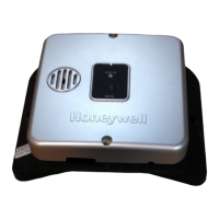
Fasten Wire (B) into its Designated Location – Protective Plate
Step 17: Tighten the slotted screw in the middle terminal location on the Protective Plate. This is shown in
Figure 97.
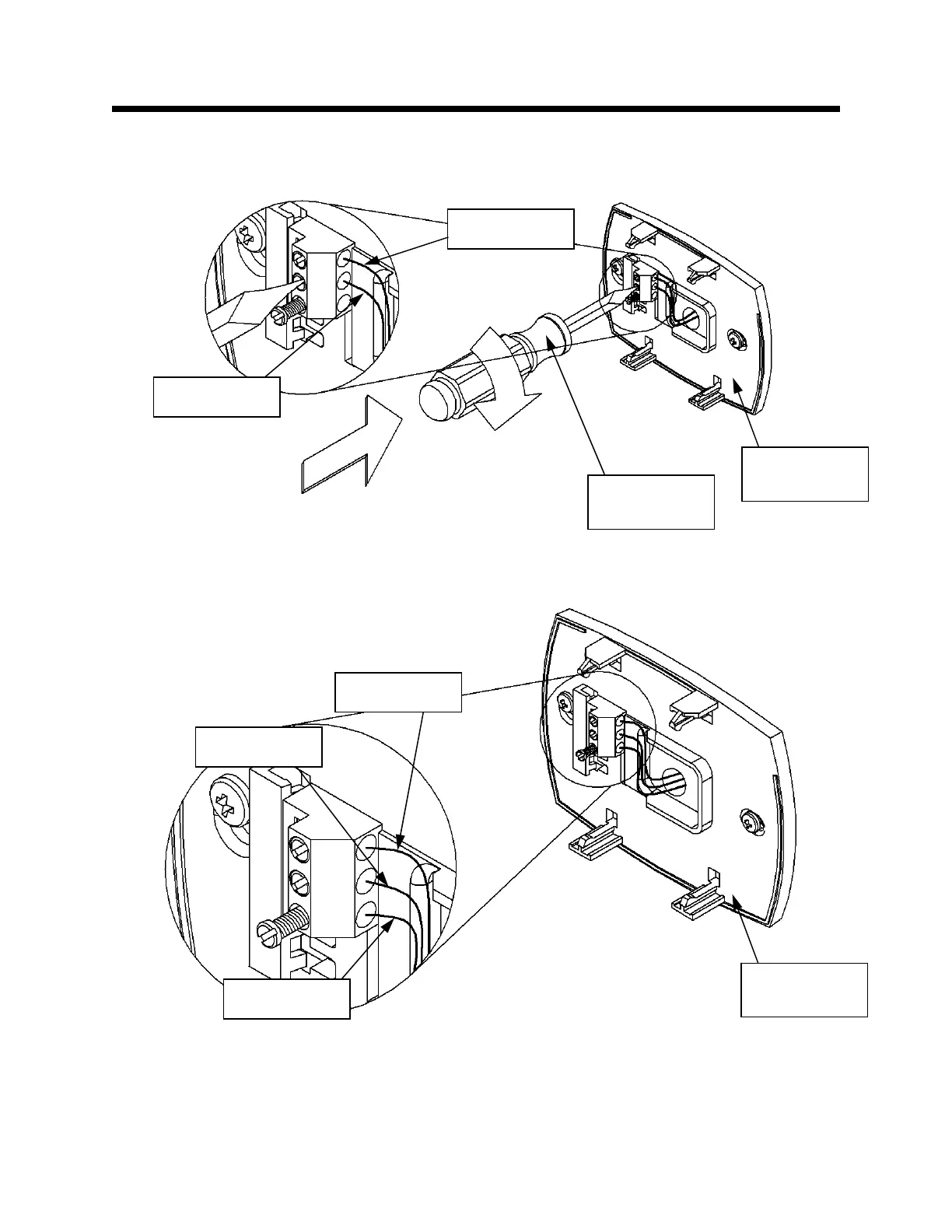
Install Wire (C) – Protective Plate
Step 18: Using wire (C), insert one end into the bottom terminal location on the Protective Plate. This is
shown in Figure 98.
Figure 98
Figure 97
Protective
Plate
Slotted head
screwdriver
Wire (A)
Wire (B)
Protective
Plate
Wire (A)
Wire (B)
Wire (C)