EasyManua.ls Logo

Bradford White D100T250 User Manual

Bradford White D100T250
44 pages
To Next Page IconTo Next Page
Page #1 background imageLoading...
Page #1 background image
Save this manual for future reference
Manual 47985A REV 08/18
SERVICE
MANUAL
Troubleshooting Guide
and Instructions for Service
(To be performed ONLY by
qualified service providers)
Models Covered
by This Manual:
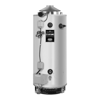
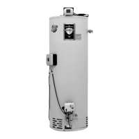
For The Bradford White
“D” Series Models:
D38T155
D75T(125,160,300)
D65T(370,399)
D80T(180,199,250)
D80T(425,505)
D100T(199,250)
D80L(399,450,505)
D100L(199,250,270,300)
D100S(199,250)
Gas Water Heaters
COMMERCIAL 24 VOLT FLUE DAMPER
SERIES WATER HEATER WITH HONEYWELL
INTEGRATED CONTROL SYSTEM
®

Other manuals for Bradford White D100T250

Question and Answer IconNeed help?

Do you have a question about the Bradford White D100T250 and is the answer not in the manual?

Bradford White D100T250 Specifications

General IconGeneral
BrandBradford White
ModelD100T250
CategoryWater Heater
LanguageEnglish

Summary

Sequence of Operation and Lockout States

Troubleshooting Common Issues

Accessing Water Heater Service Mode

Step-by-step instructions for service personnel to enter the water heater's diagnostic service mode.

Error Code Display and History Access

Explains how error codes are displayed and how to access the stored error code history.

Honeywell Integrated Control Error Code Definitions

Resetting Lockout Conditions and Malfunctions

Procedures for resetting soft and hard lockouts, emphasizing correction of the underlying fault.

Service Procedure D24-I: Thermostat Circuit Testing

Sensor Resistance and Wiring Continuity Checks

Details testing sensor resistance and checking wire harness continuity for faults.

Resetting High Water Temperature Lockout

Steps for resetting error code 65 (High Water Temperature) after addressing the cause.

Service Procedure D24-II: Pilot Operation Testing

Pilot Ignition and Gas Flow Testing

Guides on testing pilot spark, voltage to gas valve, and checking for pilot gas flow.

Pilot Burner Assembly Inspection Procedures

Procedures for inspecting the pilot shield, flame rod, and pilot orifice for proper function.

Flame Sense Lead and Microamp Output Testing

Focuses on checking the flame sense lead and measuring pilot microamp output for flame signal verification.

Service Procedure D24-III: Main Burner Operation Testing

Main Burner Ignition and Voltage Checks

Covers testing main burner ignition, voltage to the gas valve, and pilot status during heating.

Service Procedure D24-IV: Main Burner & Pilot Removal and Inspection

Service Procedure D24-IV: Control Board Replacement

Service Procedure D24-V: Flue Baffle Removal and Inspection

Service Procedure D24-VI: Anode Removal and Inspection

Related product manuals