Do you have a question about the Bradford White RG2PV75H6N19 and is the answer not in the manual?
Provides guidance for diagnosing and resolving issues with PV Series water heaters.
Critical safety information regarding fire, explosion, and personal injury.
Specifies the timing sequences for ignition, purge, and lockout states.
Details error codes and procedures for flammable vapor sensor malfunctions.
Covers faults related to pressure and blower temperature switches.
Addresses issues where flame is lost or sensed out of sequence.
Explains error codes and actions for temperature sensor issues.
Describes errors related to pilot ignition trials and flame sensing.
Interprets LED flash codes for diagnosing operational problems.
Provides further LED error code interpretations and corresponding service procedures.
Steps to test the functionality of the pressure switch and associated components.
Instructions for safely removing and installing a new pressure switch.
Procedures for testing the blower motor and its electrical connections.
Steps for testing the blower temperature switch and its operation.
Guide for replacing the blower temperature switch.
Procedure for testing the resistance of the flammable vapor sensor.
| Category | Water Heater |
|---|---|
| Fuel Type | Natural Gas |
| Capacity | 75 gallons |
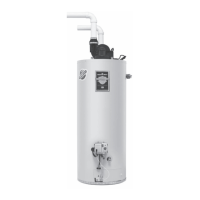
| Vent Type | Power Vent |
| Energy Factor | 0.67 |
| Width | 24 inches |
| Diameter | 24 inches |
| Warranty | 6 years |