This document is a service manual for the Bradford White Ultra Low NOx Atmospheric Vent Water Heater with Direct Spark Ignition. It provides comprehensive troubleshooting guides and instructions for service, intended to be performed only by qualified service providers.
Function Description:
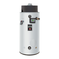
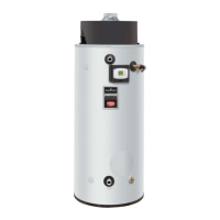
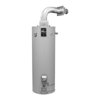
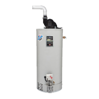
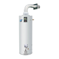
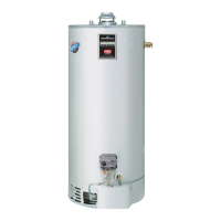
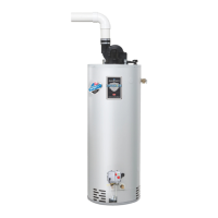
The Bradford White Ultra Low NOx Atmospheric Vent Water Heater is designed to provide a significant amount of hot water with high thermal efficiency, up to 82%. It features a quiet operation and a top exhaust vent connection, making it suitable for installation in existing locations. Unlike some other vented units, it does not require a damper to maintain heat loss during off-cycle periods. The water heater incorporates advanced design features, including an ultra-low NOx premix power burner located at the top. This burner directs a turbulent flame into a water-backed combustion chamber, ensuring thorough mixing of gas and air for optimal combustion. The combustion gases then pass through a two-pass flue system, maintaining high velocity and promoting efficient heat transfer from the flue gases to the water.
The burner's operation is managed by an electronic ignition module. This module continuously monitors the electronic thermostat, blocked vent limit switch, and flame sensor. It controls the output voltage to the blower motor, spark rod, and gas valve. The module's programming dictates the sequence of operation, including purge periods, trial for ignition, flame sensing, and lockout conditions. It also provides diagnostic information to help identify the causes of system lockouts, displaying error codes on the system display.
Important Technical Specifications:
- Models Covered: UCG(80,100)H399*(N,X) (where * denotes Warranty Years).
- Effective Date: November, 2015 (ECO 7964).
- Power Supply: Dedicated 120 VAC, 60 Hz, 15A GFI.
- Gas Supply: Minimum 1" Nat (Schedule 40 black iron pipe recommended).
- Approved Gas Type: Natural (unit must match gas type supplied).
- Gas Pressure (Nat.): 14.0" W.C. maximum static, 4.5" W.C. minimum running (recommended 7.0" W.C. min running).
- Venting System: Atmospherically Vented, Type B Venting system or approved chimney. Must follow current National Fuel Gas Code or Canadian Natural Gas and Propane Installation Code requirements.
- Minimum Clearance for Servicing: 18" from top, 24" from front, 4" sides and rear.
- Maximum Water Supply Pressure: 150 PSI.
- Thermostat Sensor: 11,900 Ohms @ 70°F, ECO opens @ 207°F Max. Redundant sensor for ECO, located inside a well for easy replacement.
- Control Display: Digital display, 24 volts. Temperature Range: 70-180°F (or °C). Used to set tank temperature, show operating status, display error codes, error code history, and limit maximum setpoint temperature.
- Control Board: Operates from 24 volts from transformer. Controls tank temperature, ignition functions, and combustion blower.
- Transformer: 120 VAC primary, 24 VAC secondary, 40 VA.
- Spark Rod Igniter: 0.22" nominal gap to the burner surface.
- Flame Sensor Output: Minimum 1 micro amp. Typical range 5 to 30 micro amps.
- Gas Valve: Negative regulation, 24 VAC, 1½" PSI max., 4.5" W.C. minimum running inlet.
- Vent Safety Switch: Normally closed, opens @ 240°F, manual reset.
- Blower: 120 VAC, 60 Hz, 1.5-3.5 amps, 8000 RPM.
- Combustion Levels: CO2: 8-11%, CO: less than 0.04% (400 PPM) air free.
- Intake Vent Length (3" pipe): Max 25 feet.
- Intake Vent Length (4" pipe): Max 50 feet. (Note: Not approved for 2-inch diameter vent pipe).
Usage Features:
- Digital Display: Attractive digital display on the control panel for setting and viewing the temperature setpoint. UP and DOWN buttons adjust the temperature. Temperature can be displayed in °F or °C.
- Integrated Control System: A single control board integrates temperature, ignition, and blower operation, simplifying wiring and reducing the number of parts.
- Direct Spark Ignition: A high voltage spark jumps from the spark rod to the burner surface to ignite the gas, eliminating the need for hot surface igniter replacements.
- Diagnostic Codes: The water heater display shows diagnostic codes in case of malfunction, aiding in troubleshooting. It also stores previous error code history.
- Sequence of Operation:
- Thermostat calls for heat.
- Combustion blower starts.
- 30-second blower pre-purge.
- Trial for Ignition (5 seconds, 3 trials):
- Flame establishing period (3 seconds): Gas valve opens, sparks ignite gas.
- Flame proving period (2 seconds): Requires minimum 1.0 microamp through flame sense rod.
- If blocked vent safety switch opens, ignition sequence stops, and error code 67 is displayed.
- Steady State Operation: Burner operates until thermostat circuit opens, gas valve closes, or blocked vent safety switch opens (leading to error code 67 and indefinite blower operation).
- Thermostat satisfied.
- Gas valve closes, burner extinguishes.
- 30-second blower post-purge.
- Lockout Conditions:
- Error Code 110 (Soft Lockout): Occurs if the main burner fails to light or prove flame after 3 ignition trials. The control waits 15 minutes, then attempts 3 more ignitions. Reset by pressing the "Reset" button for 3 seconds.
- Error Code 80 (Hard Lockout): Occurs if tank temperature exceeds 207°F. Resettable only in "Service Mode" after correcting the overheating condition.
- Error Code 67: Occurs if the vent safety switch opens. Resets automatically once the problem is corrected and the switch resets.
Maintenance Features:
- Troubleshooting Guide: Detailed flowcharts and tables for diagnosing issues based on display error codes and system observations.
- Required Tools: Manometer (liquid U-tube or digital), Multi-Meter (digital recommended, capable of measuring AC/DC volts, Amps, micro-amps, ohms), Thermometer, Water Pressure Gage, Jumper Leads, and various hand tools.
- Component Replacement Procedures: Step-by-step instructions for testing and replacing key components:
- Thermostat Circuit (Sensor)
- Combustion System (Burner Tube, Gas Valve, Blower)
- Flame Sensor
- Spark Rod (including gap adjustment)
- Ignition Module/Control Board
- Blocked Vent Switch
- Anode Rods
- Display Module
- Transformer
- Installation Check List: Ensures proper installation to prevent operational issues.
- Service Report: A form to record service details, assisting in accurate troubleshooting and technical support.
- Sensor Resistance Chart: Provides resistance values for the thermostat sensor at various temperatures (in °F and °C) to aid in testing.
- Warning Labels: Prominent warnings regarding electrical hazards (120 volt potential exposure) and hot components during service.
- Gasket Inspection: Emphasizes inspecting gaskets for tears, missing material, cracks, dirt, or debris during combustion system and burner tube replacement to ensure proper seals.
- Spark Gap Adjustment: Critical procedure for setting the spark rod gap (3/16" to 1/4") to ensure proper ignition and prevent damage.