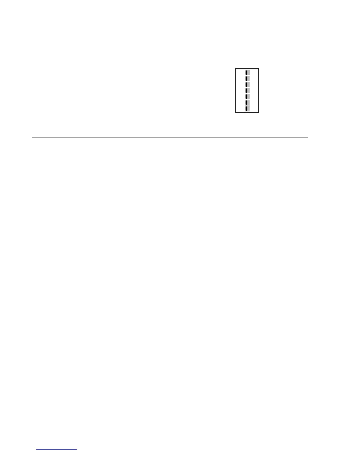
3. Set the DIP switches to meet system requirements.
Switch Label Function
1 Non-HP / Heat Pump Conventional or heat pump control of W/Y
2 Normal / Dual Fuel HP 1st stage lockout on 2nd stage call
3 Rev Valve B / O O/B terminal active in heating (B position) or cooling (O position)
4 Fan Gas / Elec & HP Fan controlled by HVAC system or panel
5 Opp Call 20 / 15 Opposite call answer time in minutes
6 Lockout None / Active 2nd stage lockout without 2 zones calling
7 Priority All / Zone 1 Changeover priority zone 1 or first call
5
System Checkout
After the wiring and configuration is complete, use the following checklist to verify the panel operation
is correct.
[ ] Make sure the Emergency Heat Switch is in the Off (right) position.
[ ] Open jumper J2 by moving cap from both pins to only one pin.
[ ] Use table and diagram in section 4 of this installer guide or inside the zone panel cover to
verify DIP switches are set properly.
[ ] Make sure no zones are calling by turning off zone 1 and zone 2 thermostats.
[ ] Apply 24 VAC power to the panel.
[ ] Verify green power LED near 24 VAC terminals is lit.
HEAT PUMP
DUAL FUEL
O
ELEC/HP
15
ACTIVE
ZONE1
NON HP
NORMAL
REV VALVE B
FAN GAS
OPP CALL 20
LOCKOUT NONE
PRIORITY ALL
7