3 Installer Manual
Wiring Terminations for model 3220
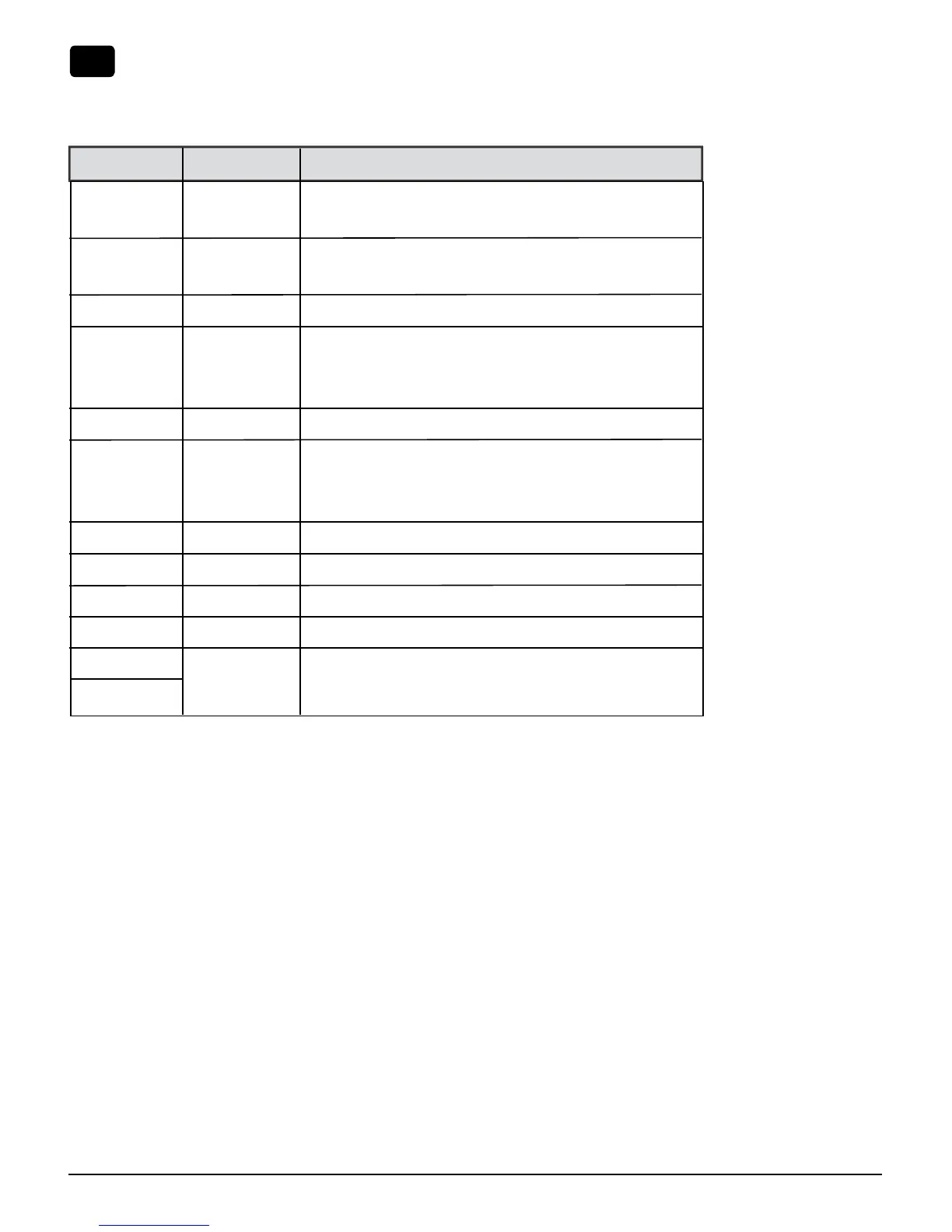
Terminal Function Description
Rc Input 24 Volt AC Cooling Transformer
(Dual Transformer Systems Only)
Rh Input Power Connection (24 Volt AC Heating
Transformer or Millivolt Power Source)
G Output Fan Control
W1 / E / W3 Output (W1) 1st Stage Conventional Heat,
(E) Emergency Heat,
(W3) 3rd Stage Auxiliary Heat
W2 Output 2nd Stage Conventional Heat
O / B / V3 Output (O) Cool Active Reversing Valve
(B) Heat Active Reversing Valve
(V3) Zone Valve Power Close
Y1 Output 1st Stage Compressor
Y2 Output 2nd Stage Compressor
L Input System Malfunction Indicator
C Input 24 Volt AC Transformer Common
S1
S2
Connecting Your Wires (continued)
3
Input Optional Remote Sensor (indoor or outdoor)

 Loading...