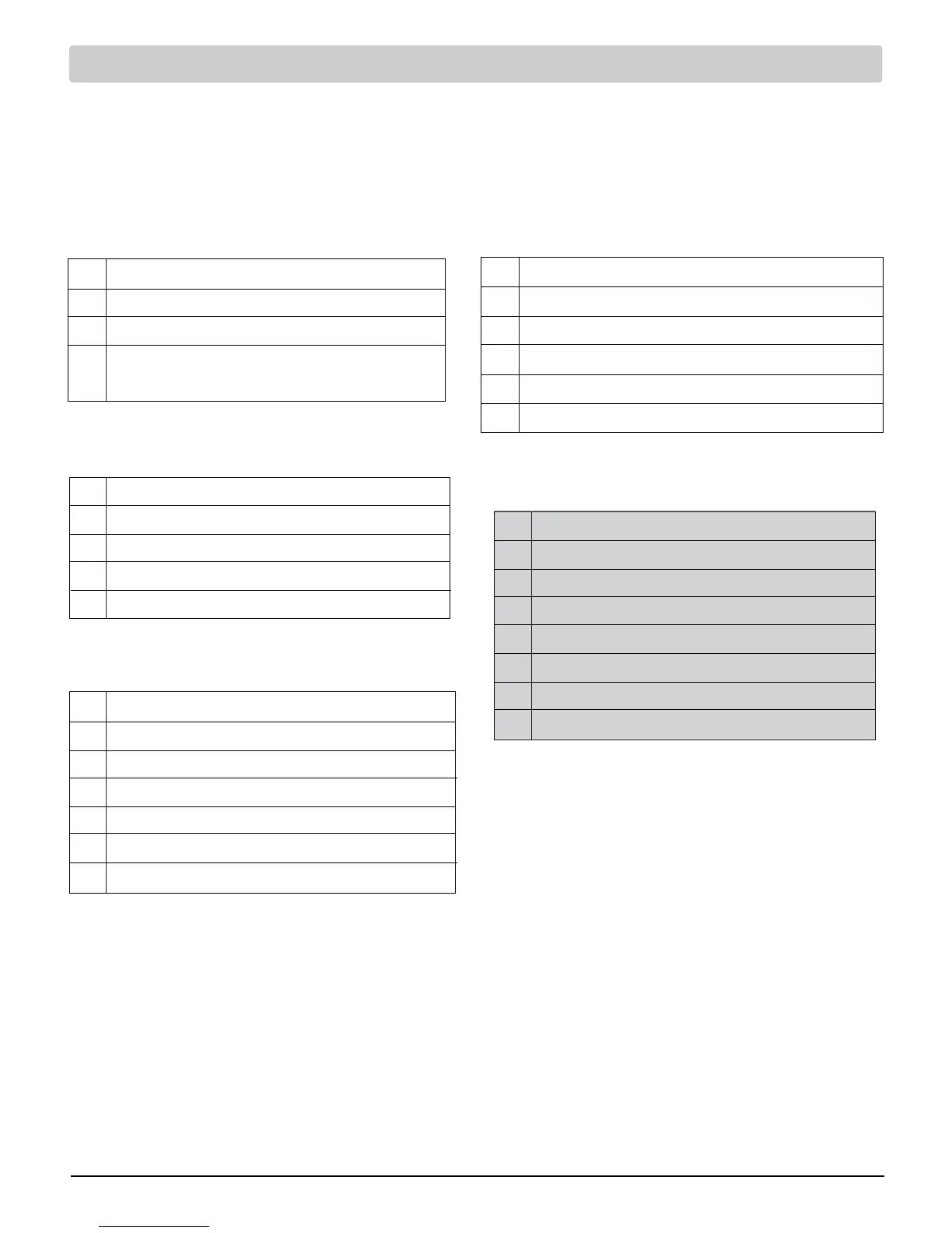
NOTES - Conventional Systems
[1] Optional 24 Volt AC common connection.
[2] Remove factory installed jumper for dual
transformer systems.
[3] In dual transformer systems, transformer
common must come from cooling transformer.
[4]
If needed for system.
Provide disconnect and overload protection
as required.
2 HEAT / 2 COOL Single or Dual transformer
Set System Type to 22CONV (3220 Only)
Rh
24 Volt AC Power (heating transformer) [note 2]
Rc
24 Volt AC Power (cooling transformer) [note 2]
W1 Heat Relay Stage 1
W2 Heat Relay Stage 2
Y1 Compressor Relay Stage 1
Y2 Compressor Relay Stage 2 [note 4]
G Fan Relay
C 24 Volt AC Transformer Common [note 1, 3]
Hydronic Heat Only
Set System Type to 1HD
Rh
24 Volt AC Power (heating transformer)
W1 Zone Valve Power Open
V3 Zone Valve Power Close
G Fan Relay [note 4]
C 24 Volt AC Transformer Common [note 1]
Hydronic Heat / 1 Cool
Set System Type to 11HD
Rh
24 Volt AC Power (heating transformer) [note 2]
Rc
24 Volt AC Power (cooling transformer) [note 2]
W1 Zone Valve Power Open
V3 Zone Valve Power Close
Y1 Compressor Relay
G Fan Relay (cooling fan only)
C 24 Volt AC Transformer Common [note 1, 3]
Installer Manual 4
Heat Only or Millivolt
Set System Type to 11CONV
Rh Power Connection
W1 Heat Relay
G Fan Relay [note 4]
C 24 Volt AC Transformer Common
[note 1]
1 HEAT / 1 COOL Single or Dual Transformer
Set System Type to 11CONV
Rh
24 Volt AC Power (heating transformer) [note 2]
Rc
24 Volt AC Power (cooling transformer) [note 2]
W1 Heat Relay
Y1 Compressor Relay
G Fan Relay
C 24 Volt AC Transformer Common [note 1, 3]
Typical Wiring Configurations
NOTE: The “System Type” option will be configured in the Installer Settings section. Shaded areas do not
apply to the 3020.
Conventional Systems
 Loading...