EasyManua.ls Logo

Braeburn Builder 1000 User Manual

Braeburn Builder 1000
7 pages
To Next Page IconTo Next Page
Page #1 background imageLoading...
Page #1 background image
WARNING
Important Safety Information
1
Builder Series
Non-Programmable Thermostats
Single Stage Heat / Cool
Conventional and Heat Pump
Multi-Stage 2 Heat / 1 Cool
Conventional and Heat Pump
Always turn off power to the air conditioning or heating system prior to
installing, removing, cleaning or servicing thermostat.
This thermostat requires either 24 Volts AC Power or two (2) properly installed
“AA” alkaline batteries for normal operation and control of the heating or
cooling system. Refer to “Low Battery Detection and Replacement” section for
more information.
This thermostat should only be used as described in this manual. Any other
use is not recommended and will void the warranty.
Specifications
Installation
Testing Your New Thermostat
Programming User Settings
Temperature Adjustment
Additional Operation
Features
Battery Replacement
Troubleshooting
Wiring Diagrams
1
2
3
4
5
6
7
8
9
1
Specifications
• Electrical Rating: 24 Volt AC (18-30 Volt AC)
1 amp maximum load per terminal
2 amp total maximum load (all terminals) (Model 1000, 1000NC)
3 amp total maximum load (all terminals) (Model 1200, 1200NC)
• Control Range: 45˚ - 90˚ F (7˚- 32˚ C)
Accuracy: +/- 1˚ F (+/- .5˚ C)
AC Power: 18-30 Volt AC
• DC Power: 3.0 Volt DC (2 AA Alkaline batteries included)
Model 1200, 1200NC: Compatibility with low voltage multi-stage gas, oil or
electric heating or cooling systems, including multi-stage heat pumps.
Terminations, Model 1000, 1000NC: Rc, Rh, B, O, Y, W, G, C
Terminations, Model 1200, 1200NC: R, O, B, C, Y1, E/W1, G, W2
1
Specifications
cont.
Installation
2
MODEL
Before Installing, Programming or Operating,
PLEASE READ ALL INSTRUCTIONS
Model 1000, 1000NC: Compatibility with low voltage single stage gas, oil or
electric heating or cooling systems, including single stage heat pumps, can
also be used on 250mv to 750mv millivolt heating only systems.
Old Terminal from
Existing Thermostat
New Terminal for
New Thermostat
(1000, 1000NC)
New Terminal for
New Thermostat
(1200, 1200NC)
Terminal
Description
V or Rc Rc Cooling
Transformer
M, 4, Rh, or R Rh Heating
Transformer
R, V-VR or VR-R R 24 VAC
B B B Reversing Valve
(Heating)
O O O Reversing Valve
(Cooling)
Y, Y1 or M Y Y1 Cooling or
Compressor for
HP System
E, H, W, or 4 W E/W1 1st Stage Heat
or Emergency Heat
G or F G G Fan Control
C, X or B C C 24 VAC Common
1000, 1000NC
MODEL
1200, 1200NC
Replacing Existing Thermostat
Most thermostats have three parts:
The cover, which may snap or hinge over the existing thermostat.
The electronics or body, which controls the existing system.
The sub-base, where the wires attach through the wall to the existing system.
1. Always turn off power to the air conditioning or heating system prior to
removing existing thermostat.
2.
Carefully remove the cover and electronics body from the old thermostat sub-base.
Depending on the brand, these parts may pull off or need to be unscrewed. The
old sub-base should remain wired and on the wall until steps 4 and 5.
3. Label every old wire with the letter of the connection to which the wire is
attached. Example letters are R, M, Y etc. Depending on the brand of the old
thermostat, your letters may be different.
4. After labeling the old wires, loosen each connection and remove them from old
sub-base. Secure the wires to prevent them from slipping into the hole in the wall.
5. Remove the old sub-base from the wall, again being careful that the wires do
not slip into the hole in the wall.
6. Use the chart below to determine the new thermostat connections. As an
example, if the old thermostat had a G connection, it goes to G on the new
thermostat. Note the chart includes information for Braeburn
®
1000(NC) and
1200(NC) thermostats. Be sure to use the correct column for the new thermostat.

Other manuals for Braeburn Builder 1000

Question and Answer IconNeed help?

Do you have a question about the Braeburn Builder 1000 and is the answer not in the manual?

Braeburn Builder 1000 Specifications

General IconGeneral
BrandBraeburn
ModelBuilder 1000
CategoryThermostat
LanguageEnglish

Summary

Specifications

Electrical Ratings, Control Range, and Accuracy

Details electrical ratings (24V AC), temperature control range (45-90°F), and accuracy (+/- 1°F).

Power Options and Model Compatibility

Covers AC/DC power and compatibility for 1000/1000NC (single-stage) and 1200/1200NC (multi-stage).

Installation

Replacing Existing Thermostat

Step-by-step guide for removing an old thermostat and preparing for new installation.

Testing Your New Thermostat

Safety Warnings Before Testing

Critical safety advice to prevent damage, including avoiding short circuits and low-temp cooling.

Programming User Settings

Default Thermostat Settings Overview

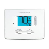
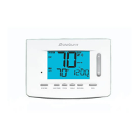
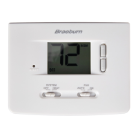
Presents default operational settings for mode, temperature, scale, battery status, and differentials.

Setting Temperature Differentials

Instructions to adjust first and second stage differentials for optimal system response.

Temperature Adjustment

Review and Change Set Temperature

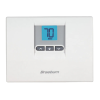
Guidance on viewing current set points and adjusting desired heating or cooling temperatures.

Additional Operation Features

Compressor Protection and Status Indicators

Details compressor protection, non-volatile memory, and display status indicators (HEAT, COOL, AUX).

Low Battery Detection and Replacement

Explains low battery warnings and the requirement for AA alkaline batteries for proper operation.

Battery Replacement

Replacing the Batteries

Step-by-step instructions for opening the cover and replacing the AA alkaline batteries.

LIMITED WARRANTY

Warranty Coverage and Limitations

Outlines the 5-year/2-year warranty for defects, excluding batteries and improper installation.

Warranty Facility and Contact Information

Provides details for returning units for warranty service and technical assistance contact.

Troubleshooting

Display Errors and Blank Screens

Resolves issues with blank displays, HI/LO indicators, and NO AUX SET messages.

System Response and Fan Operation Issues

Addresses problems with heating/cooling not starting, continuous fan operation, and wiring checks.

Room Temperature and System Response

Troubleshoots room temperature accuracy and system response to thermostat commands.

Wiring Diagrams

1000/1000NC Single Stage Conventional Systems

Wiring diagrams for 1000/1000NC models in single stage conventional setups.

1000/1000NC Single Stage Heat Pump System

Wiring diagram for 1000/1000NC models in single stage heat pump configurations.

1200/1200NC Multi-Stage Heat Pump Systems

Wiring diagram for 1200/1200NC models in multi-stage heat pump setups.

1200/1200NC Conventional Systems

Wiring diagram for 1200/1200NC models in conventional configurations.

Related product manuals