Page 23Page 22
Lift Installation
Tower Microswitch Adjustment
Installer Verication
Compatibility between the lift and the vehicle
The installer shall conrm the compatibility between the lift and the vehicle.
Static Test
Deformation
The unladen platform is positioned mid-way between ground level and vehicle oor level and
measurements are taken of the height of the platform and its angular attitude relative to the vehicle oor.
A load of “B” kg (see table on following page) is applied to the platform and subsequently removed.
By repeating measurements of the height and attitude of the platform, verify that no permanent
deformation has occurred in any part of the lift or its attachment to the vehicle which could affect the
function of the lift.
Drift
A load of “B” kg (see table on following page) is applied to the platform, positioned at oor level.
Measurements are taken of the height of the platform and its angular attitude relative to the vehicle oor.
These measurements are repeated after a 15 minute test period.
Verify that the vertical drift of the platform between the two measurements has not exceeded 15mm.
Verify that the angular drift of the platform between the two measurements has not exceeded 2º.
Test to Verify that the Lift Cannot Lift Excessive Load
A load of “B” kg is applied to the platform, positioned at ground level. Actuate the UP control and verify
that the platform does not lift (tilt is permissible).
1. Lower platform to the ground.
2. Place “B” kg (see table on following page) at center of platform.
3. Press UP switch and verify platform does not lift (tilt is permissible).
4. If platform does not lift, proceed to Dynamic Test. If platform does lift, proceed to step 5, pump relief
valve adjustment is necessary.
5. Access relief valve (see illustration on following page). Loosen 9/16" hex nut on the relief valve
adjustment screw (do not remove hex nut).
6. Turn adjustment screw counterclockwise 1/8 turn.
7. Press UP switch and verify platform does not lift (tilt is permissible).
8. If platform does not lift, tighten 9/16" hex nut (do not turn relief valve adjustment screw while
tightening hex nut). If platform does lift, repeat steps 6 through 8
Review adjustment
procedures below and
adjust as needed only.
Left (rear) pump lift depicted.
Right (front) pump lift is a
mirrored image.
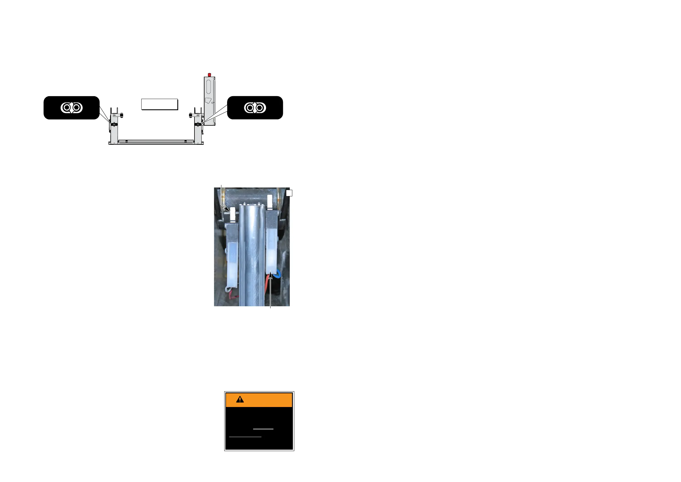
Tower 3 (Count) Switch Adjustment
Cycle Counter Switch
1. Position platform approximately 25 mm below
oor level position using the pendant control.
2. View the Tower 3 microswitch inside the lift
tower (see Photo H). Turn switch adjustment
screw counterclockwise until microswitch no
longer contacts the activation plate.
3. Observe the cycle count number on the LCD
display. Slowly turn switch adjustment screw
clockwise until the microswitch activates
(clicks) and the number on the cycle counter
LCD has changed.
Tower 4 (Fold) Switch Adjustment
Partial Fold
1. Position platform at 45˚ angle using the manual
hand pump or pendant control.
2. View the Tower 4 microswitch inside the lift
tower (see Photo H). Turn the switch adjust
-
ment screw in or out as needed until the radius
of the microswitch blade rides on the apex of
the activation plate.
3. Verify proper adjustment. Criteria below must
be met.
Proper Adjustment Criteria:
• Apply pressure (push down) on outboard end
of platform by pressing the hand pendant
FOLD switch. The platform should not fold
(stow) with light pressure applied.
• When folding fully, the platform should stow
tightly (snug with stow blocks).
TOWER
1
TOWER
2
31130
TOWER
3
TOWER
4
31131
TOWER
2
TOWER
1
32942
TOWER
4
TOWER
3
32943
Figure E
TOWER
2
TOWER
1
32942
TOWER
4
TOWER
3
32943
Improper microswitch
adjustment may
result in serious
bodily injury and/or
property damage.
Radius of Tower 4 microswitch
blade activated by apex of
activation plate.
Tower 3 Microswitch
Platform Angle Adjustment:
Check platform angle after
Tower Microswitch Adjust-
ment procedures.
Platform Stop Blocks: En-
sure both stop blocks are
making full contact with the
vertical arms.
H