Page 25Page 24
Installer Verication
Dynamic Test
With “A” kg (see table below) applied to the platform, verify that the lift is able to operate throughout its
full range of normal lifting and lowering.
1. Lower platform to the ground.
2. Place “A” kg (see table below) at center of platform.
3. Press UP switch and verify that the lift is able to operate throughout its full range of normal lifting and
lowering movements.
4. If platform is able to operate throughout its full range of normal lifting and lowering movements, no
adjustment is necessary. If platform does not lift, proceed to step 5, pump relief valve adjustment is
necessary.
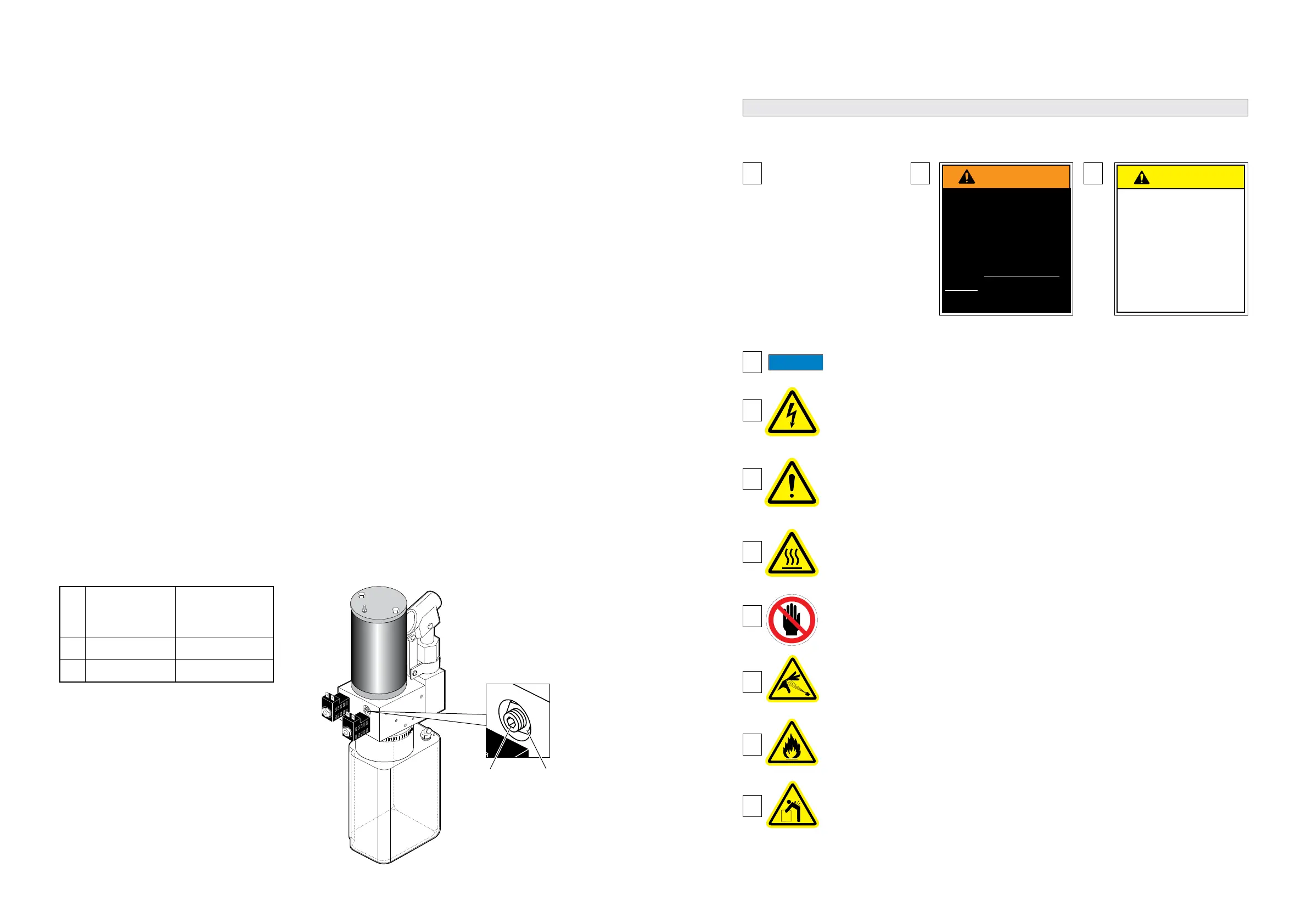
5. Access relief valve (see illustration below). Loosen 9/16" hex nut on the relief valve adjustment
screw (do not remove hex nut).
6. Turn adjustment screw clockwise 1/8 turn.
7. Press UP switch and verify lift is able to operate throughout its full range of normal lifting and
lowering movement.
8. If lift does not operate throughout its full range, repeat steps 6 through 8. If lift does operate
throughout its full range, tighten 9/16" hex nut (do not turn relief valve adjustment screw while
tightening hex nut).
Test of Operations and Safety Functions
All functions of the lift and operations of all safety devices are veried after the static and dynamic tests
have been completed. These tests do not apply to pipe break valves nor non-resettable safety devices
such as electrical fuses (These items are the subject of a manufacturer’s type test).
9/16"
Hex Nut
Relief
Valve
Adjustment
Screw
A 272 363
B 340 454
Lift With
272kg (600 lb.)
Load Rating
Lift With
363kg (800 lb.)
Load Rating
Lift Operation Safety
Safety Symbols
SAFETY FIRST! Know That....
C
CAUTION
CAUTION
CAUTION
CAUTION
This symbol indicates
important information
regarding how to
avoid a hazardous
situation that could
result in minor person-
al injury or property
damage.
B
This symbol indicates
important safety in-
formation regarding a
potentially hazardous
situation that could re-
sult in serious bodily
injury and/or property
damage.
D
Additional information provided to help clarify or detail a specic subject.
The information contained
in this manual and
supplements (if included),
is provided for your use and
safety. Familiarity with proper
installation, operation, mainte-
nance and service procedures
is necessary to ensure safe,
trouble free lift operation.
Safety precautions are provided
to identify potentially hazardous
situations and provide instruc-
tion on how to avoid them.
A
E
F
This symbol indicates that there are dangerous energy levels present inside the
enclosure of this product. To reduce the risk of re or electric shock, do not attempt
to open the enclosure or gain access to areas where you are not instructed to do
so. Refer servicing to qualied service personnel only.
This symbol indicates that a condition where damage to the equipment resulting
in injury to the operator could occur if operational procedures are not followed. To
reduce the risk of damage or injury, refer to accompanying documents, follow all
steps or procedures as instructed.
These symbols will appear throughout this manual as well as on the labels posted on your lift.
Recognize the seriousness of this information.
G
This symbol indicates that a condition where injury or damage could occur if
contact is made with the hot surface.
36512
H
This symbol indicates an area to avoid bodily contact to prevent injury.
36514
I
K
J
This symbol indicates the presence of a re hazard. Avoid open ames or
sparks when working with ammable materials to prevent injury or damage.
This symbol indicates the presence of high pressure hydraulic hoses. Use
appropriate personal protective equipment when working on hydraulic system.
This symbol indicates a device weighs in excess of 139kg (306 lbs).
Use of a fork lift or hoist is required.
36513