8
Device Connections
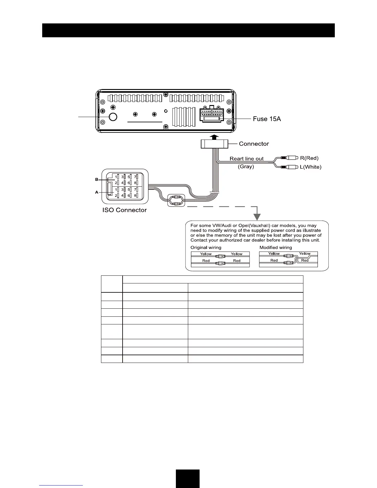
Wiring Diagram
ANTENNA
Location
Function
Connector A Connector B
1 Rear Right (+) / Purple
2 Rear Right (-) / Purple with Black Stripe
3 Front Right (+) / Gray
4 Battery 12V(+) / Yellow Front Right (-) / Gray with Black Stripe
5
ANT/AMP control / Blue
with white stripe
Front Left(+) / White
6 Front Left(-) / White with Black Stripe
7 ACC+ / Red Rear Left (+) / Green
8 Ground / Black Rear Left (-) / Green with Black Stripe
 Loading...